
WDK-ERA-STROBES User Manual
Setup, pairing, and troubleshooting for the WDK-ERA-STROBES Business & Warehouse Doorbell Kits with Bright Flashing Strobe Light.
- WDK-ERA-STROBE Kit
- Owner’s Manual
- This device complies with Part 15 of the FCC rules, Operation of this device is subject
- to the following conditions: 1. This device may not cause harmful interference. 2. This
- device must accept any interference, including interference that may cause unde-
sired operation.
Introduction
- The ERA-UTX is a Universal Transmitter compatible with the ERA-DCRX
- Receiver and is included in the kit. The ERA-UTX has several methods
- of activation. First, it has a push button that can be used as a panic
- button or doorbell button. The ERA-UTX also has terminals for a normally
- open (N/O) or normally closed (N/C) input. These inputs can be used
- with any detector contacts. There is also a magnetic contact that can
- be used for doors or windows. When the transmitter is activated, it will
- send a signal to the receiver which will sound one of 12 different tones for
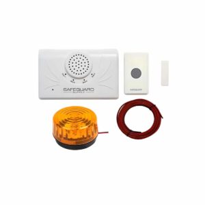
a few seconds, and trigger the connected strobe light to flash. What;'s in the Kit:
- ERA-UTX transmitter with mounting bracket & hardware
- ERA-DCRX
- Strobe light
- Wire (if needed)
Helpful Notes
- Each receiver is capable of pairing with four (4) transmitters per zone.
- Each zone features 1 x 12V DC output.
- Output duration for the 12V DC output may be set to 5 sec, 10 sec, 1 min, & 2 min. The receiver features 1 x C-Form relay assignable to one or multiple zones & will take on the duration of the 12V DC output.
Volume Control
4 levels plus mute, plus off.
- Each transmitter must be paired to a zone on the receiver.
- Each zone is programmed to the "ding-dong" sound from the factory. User may change this melody.
- When transmitter battery is low, it sends a signal to the receiver when triggered & the corresponding LED on the receiver will continue to flash for 10 minutes & the receiver will double-play the melody..
Battery Installation
- 1. Flip over the ERA-UTX & remove the gray
- silicon grommets (one per corner). The screws
- are under the grommets.
- 2. Remove the four screws on the back of the
- case and open to find the battery compartment.
- (Figure 1)
- 3. Remove top half of case from lower case.
- 4. Install the included CR-2 battery in the holder
(Figure 1). 5. Re-tighted screws & insert grommets.
- 6. Note: When battery gets weak, it will cause
- paired zone to flash LED on receiver for 10
- minutes when triggered.
- (Figure 1)
- LED Indicator Light in Button:
- The default setting is for the LED indicator to light up for two seconds
when the ERA-UTX is activated.
Pairing the Transmitter
- (Always test unit prior to installation)
- The transmitter works with the ERA-DCRX receiver & basic programming
- calls for the user to pair the transmitters with a receiver & select a
- melody for the transmitter to instruct the receiver to play when
- triggered.
- For quick setup, however, each zone defaults to a basic "ding-dong" sound allowing
- you to easily pair the transmitter for a faster set up process.
- 1. On the ERA-DCRX receiver, hold down the "mode" (left button in
- figure 2 below) button until you hear a short tone sound & the "zone
- 1" LED flashes.
- 2. If you are programming the transmitter to zone 1, press the gray
- button on your transmitter. You will hear the receiver play a short
- musical note (zone 1 will continue to flash).
- 3. To program a transmitter to a different zone, press the "zone" button
- on the receiver to scroll to the appropriate zone . The zone you want
to program will flash. Repeat step 2 above. 4. Once you have programmed all the zones move to the next step.
- 5. To exit program mode, hold down the "mode" button until you hear
- a short tone sound (approx 3 sec)
- (Figure 2)
Changing the Melody
- By default, each zone is programmed by the factory
- to play the ding-dong sound
- 1. Hold down the "zone" button until you hear a short tone & all
- LEDs on front panel of receiver are red (approx 3 seconds). The
- zone you are programming will flash.
- 2. Press the "volume" button to scroll through the 12 available
- melodies for selection. Once you find a melody you like, move to
- step 3.
- 3. Press the "zone" button to scroll to the next zone & repeat step 2
- to program a melody to other zones.
- 4. Once you have programmed a melody to all necessary zones,
- move to step 5.
- 5. Hold down the "zone" button until you hear a short tone sound
- (approx 3 seconds) notifying the receiver is out of melody
programming mode. Volume, Mute, Off: The volume button on the side of the receiver controls the four different volume levels, mutes & turns off the receiver. Pushing the volume button controls these functions.
- When all four zone LED lights are red, this indicates maximum volume.
- Three zone LED lights indicate the third volume level.
- Two zone LED lights indicate the second volume level.
- One zone LED light indicates the minimum volume level.
- No zone LED lights & a red power indicator light means the sound is muted.
- No LED lights (no zone LED or power indicator) means the unit is off. Pushing volume again turns it back on to max volume. --- page break --- Erasing
Programming
(memory):
- 1. Hold down "mode" button until you hear a short tone & the zone 1
- LED flashes.
- 2. Hold down the "mode" & "volume" button simultaneously until all
- LEDs stop flashing & you hear a short melody sound
- (approximately 5 seconds).
- 3. All LEDs will stop flashing & only the green LED power indicator will
display. The memory is now erased. Using the Magnetic Contact: The magnetic contact can be used on most doors/windows with a gap of less than ½ inch.
- Mount the push button on the door jam with the screws provided.
- Mount the magnet on the door (within ½” of the push button) with the screws provided.
- After mounting the magnet on the door snap the cover on the magnet case.
- The magnetic contact can be used on either side of the push button. (Figure 3) (Figure(Figure 33))
Mounting
- The transmitter can be mounted to any wall using the mounting bracket. (Figure 4)
- The mounting bracket is located on the back of the ERA-UTX and can be removed by simply sliding it off.
- Position the bracket were you would like it and place two screws in the holes MOUNTING provided. To place the ERA-UTX back BRACKET simply slide it over the bracket.
- If mounting the ERA-UTX outdoors it is recommended to place the silicone plugs in the screw holes at the back of the case to prevent moisture from entering the case. (Figure 4) Using the Relay on the ERA-UTX: The ERA-UTX can be activated by any type of detector which provides a normally open (N/O) or normally closed (N/C) output. 1. Locate the terminals at the bottom of the case. (Figure 5) 2. Insert the wires through the silicone gasket and make the connection on the terminals. 3. For a normally closed (N/C) connection, connect the wires to· the NC and Common (center) terminals. 4. For a normally open (N/O) connection, connect the wires between the NO and Common (center) terminals. (Figure 5) Using Multiple Devices on the ERA-UTX Relay: TERMINALS
- If multiple normally closed (N/C) contacts are to be used, they should be run in series to the N/C contacts.
- If multiple normally open (N/O) contacts are used, they should be run in parallel to the N/O contacts.
- Note: Both N/O and N/C contacts can be used simultaneously along with the magnetic contact and push button. Connecting a 12V DC Strobe to the ERA-DCRX Receiver The ERA-DCRX receiver features a live 12V DC output for each of the four zones of the receiver. In this kit, the Strobe Light will be connected to a zone of the ERA-DCRX receiver. To access the live 12V DC outputs and C-Form relay, separate the top half of the receiver case from the lower half. The outputs and relay are located on the PC board and are shown below. (Figure 6)
Pairing the Transmitter
per the instructions for that transmitter.
- Each zone features 1 x 12V DC output that is activated when that zone is triggered. The positive (+) & negative (-) screws for each output are shown in figure 7 below.
- The output duration for the 12V DC output may be set to 5 sec, 10 sec, 1 min, & 2 min by adjusting dip switches (Figure 7). The duration setting applies to all zones.
- The C-Form Relay, labeled "Relay" (Figure 6), may be associated with a specific zone or multiple zones & will take on the duration of the 12V DC output.
- 12V DC output current: 400mA maximum.
- The form “C” relay is rated for 24 VDC at 3 Amp maximum current.
- Form "C" relays DOES NOT supply power to external device. (Figure 6) (Figure 7) 1. Unplug the receiver & separate the top half from the lower half of the case. 2. Located the positive (+) and negative (-) wires on the strobe. The Red is the positive wire & the negative wire is black/red stripped. 3. Locate the external 12V DC terminal connection block that corresponds to the respective zone on the ERA receiver. (Figure 6). 4. Loosen the positive (+) and negative (-) screws for the zone on the receiver one you are connecting the strobe light to. For example, if a push button is paired to zone 1, and you want the siren to sound for zone 1, wire the siren into the terminal block for zone 1. 5. Insert the positive wire on the strobe to the positive screw on the zone terminal block and negative wire on the strobe to the negative screw on the zone terminal block. 6. Re-tighten screws on the terminal blocks of the ERA-DCRX receiver. 7. Plug in the receiver. 8. to ensure the transmitter triggers the receiver and the accessory is triggered by the 12V output on the ERA-DCRX. 9. Ensure the volume is turned on the receiver, the battery is installed in the transmitter, and the transmitter is programmed to the receiver. 10. Snap the cover back on the ERA-DCRX. TECHNICAL SUPPORT If you encounter any difficulty in the operation of this product after reading the manual, please contact us. You can reach us by phone at 904-245-1184 from 8:00 AM to 5:00 PM Monday through Friday (Eastern Standard Time). We will be happy to answer your questions and help you in any way we can.
Warranty
Safeguard Supply warrants this product to be free of defects in material and workmanship for a period of one year from the date of purchase. This warranty does not cover damage resulting from accident, abuse, act of God or improper operation. If this product does become defective, simply return it to Safeguard Supply.
Please include a note describing the troubles along with your name and return address as well as the original sales receipt. If the product is covered under warranty it will be repaired or replaced at no charge. If it is not covered by warranty, you will be notified of any charges before work is done.