
Product manual
SBB-4000 User Manual
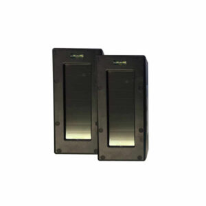
Setup, pairing, and troubleshooting for the SBB-4000 Dakota Alert BBT-4000 Solar Powered Break Beam Sensor Pair.
- Dakota Alert
- WIRELESS SECURITY EQUIPMENT
- Solar Break Beam
Transmitter SBB-4000 USER GUIDE
--- page break ---
TOOLS NEEDED:
- Philips Screwdriver
- 7mm Wrench or an Adjustable Wrench NOTE: Remove the protective plastic covering the lenses and solar panels
What's Included
- Break Beam Pair “A” and “B” (2 sensors)
- (8) M4x10 Pan Head Screws with Flat Washers and Lock Washer
- (8) M4x40 Pan Head Screws
- (8) M4 Nut
- (4) Metal Pipe Mounts
- (4) Pipe Mount Rubber Adapters
- (2) “C” Mounting Brackets
- User Guide X 8 M4x10 Pan Head Screws with Flat Washers and Lock Washers X 8 M4x40 Pan Head Screws with Nuts X 4 Metal Pipe Mounts X 4 Pipe Mount Rubber Adapters BACK OF BEAMS A B X 2 “C” Mounting Brackets --- page break --- NOTE: It is recommended to charge both the “A” and “B” unit via a USB Micro charger (not included) for about 4-6 hours before starting the initial set-up. PAIRING THE SENSORS: 1. Before mounting the sensors in a permanent location, start by placing them on a table or other flat surface about 6 to 12 inches apart with the three IR lenses pointing towards each other. 2. Press and release the power button on the “B” sensor. The LED will start flashing. 3. Press and release the power button on the “A” sensor and the LED will start flashing green. 4. When the LED stops flashing on the “A” sensor, the pairing is complete (about 30 seconds). 5. Test the pairing by completely blocking the beams. A piece of carboard can be used or physically move the beams so they are not aligned. The LED on the “A” sensor will flash for about two seconds. BACK FRONT IR LENSES USB Rubber Charging Port Plug LED Light Power Be sure to re-insert rubber plug Button before mounting permanently --- page break --- CODING THE RECEIVER: 1. The SBB-4000 can send a signal to any of the Dakota Alert 4000 series receivers. 2. Please refer to your receiver manual for coding instructions of your particular receiver. 3. To activate the SBB-4000 to send a signal to your receiver, either break the beams while they are paired or quickly press and release the power button on the “A” sensor. A signal will be sent to the receiver for code learning. 4. If coding more than one set of beams to a receiver, repeat steps 2 and 3 for each additional pair of beams. SETTING REMINDER SIGNAL FOR CONTINUOUSLY INTERRUPTED BEAMS: 1. If the beams are continuously interrupted, the “A” sensor will send a reminder signal to the receiver. The factory default is to send a signal every 20 seconds if the beams are continuously interrupted. 2. To change the reminder duration to 5 minutes, press and hold the power button of the “A” sensor for 5 seconds then release. The LED will start flashing red. 3. To change back to the 20 second reminder duration, press and hold the power button of the “A” sensor for 5 seconds then release. The LED will now flash green. 4. After you are finished pairing, coding, and setting the reminder time, insert the rubber plugs into the holes near the power button on both the “A” and “B” side. To ensure that water does not enter the beams during outdoor use. Power Button of “A” Unit Be sure to re-insert rubber plug before mounting permanently --- page break --- MOUNTING THE SENSORS: Before mounting, choose a suitable location:
- The recommended mounting height is about 3 feet. This will help to avoid false alerts from small animals crossing under the beams.
- The sensors can be mounted up to 300 feet apart facing each other.
- Mount the sensor on a solid object such as a wall, post, or pipe. Sensors should be facing each other at approximately the same height CORRECT ALIGNMENT INCORRECT ALIGNMENT Mounting to a flat surface
- Use appropriate screws or fasteners (not included) to mount the back of the “C” bracket directly to a flat surface such as a wall or wood post. Mounting to a pole or pipe
- Use the provided screws (M4x40 Pan Head Screw and Nut), pipe mount and rubber adapter to connect the “C” bracket to the pipe. Top View of Side View of Pipe Mount Pipe Mount M4 NUT METAL PIPE PIPE MOUNT PIPE MOUNT RUBBER ADAPTER M4x40 PAN HEAD SCREW --- page break --- MOUNTING SENSORS TO THE “C” BRACKET: 1. Make sure both the “A” and “B” units are powered on and the rubber plugs are inserted into the power button recess. 2. Use the provided small screws, split ring lock washers and flat washers to mount the “A” and “B” beams to the “C” brackets. 3. Align the “A” and “B” units so the lenses are pointing towards each other. 4. The beams can be rotated inside the “C” bracket by loosening the screws on the top and bottom of the sensor to help achieve alignment. After rotating the sensors re-tighten the screws. 5. If the beams are paired, you will get a signal when you walk between the beams. If you get a signal every 20 seconds (5 minutes optional), this is the reminder signal and the beams are not aligned. Slightly reposition the beams until the reminder stops and the beams are activated by walking between them. M4x10 Screw M4x10 Screw Lock Washer Lock Washer Flat Washer Flat Washer Mount with Bubble on Top Loosen Screw To Rotate Sensor 2 screws 2 screws WHEN MOUNTED, THE LEVEL BUBBLE MUST BE TOWARDS THE TOP --- page break --- RECHARGING THE BEAMS: The beams will charge automatically outdoors with the built-in solar panels. If the beams are used in an interior location with no light, they can be manually charged. 1. For interior locations, remove the rubber plug from the power button. 2. Locate the USB Micro charging port. 3. Connect a USB Micro charger (not included) to the port. 4. Once finished charging insert the rubber plug back into the recess. NOTE: You can either leave the charger connected indefinitely or you can fully charge the beams periodically. When the beams are fully charged the built-in batteries will usually hold a charge for about a month, depending on activations. USB Charging Port Charging Port (Under Rubber Plug) Be sure to re-insert rubber plug before mounting permanently --- page break --- TROUBLE SHOOTING: If you are getting false signals:
- Make sure there are no tree branches or other obstructions that may be periodically blocking the beams.
- If the signal is occurring every 20 seconds (5 minutes), this indicates that the beams are either misaligned or there is something continuously blocking the beams.
- You may receive false signals during extreme rain, snow, or fog.
- If the false signals are occuring every 20 seconds (5 minutes) the battery may be dead in the B unit. Manually charge the B unit via USB micro for several hours, then turn on the B unit by pressing the power button. If you are getting no signals:
- Make sure both the A and B units are powered on.
- Make sure the beams are coded to your receiver.
- Make sure the beams are charged. You may need to manually charge with a USB Micro charger.
- Move the beams closer to your receiver.
- Keep the A sensor away from large metal objects that may interfere with the radio signal.
Specifications
- Power source: 18650 rechargeable lithium battery, solar charger or USB Micro (not included).
- Frequency: 433.92 MHz
Wireless Range
up to 1 mile*
- Maximum detection range: Up to 300 feet.*
- Operating temperature: -20 to 120F. *Actual range will vary depending on local terrain and obstructions. Tech Support: If you have any troubles using this product after reading the manual, please contact us. You can reach us by phone at 605-356-2772 from 8:30 Am to 5:00 PM Monday through Friday (Central Standard Time). We will be happy to answer any questions and help in any way we can. Safety information:
- Only use this product for the detection of moving objects such as people or vehicles.
- Do not disassemble or attempt to repair the product.
- Do not install this unit with any other infrared detectors as this may cause false signals.
- Do clean and inspect the beams regularly for proper use. If any trouble is found, please contact Dakota Alert, Inc. --- page break ---
Warranty
- Dakota Alert warrants this product to be free of defects in materials and
- workmanship for a period of one year from the date of purchase. This warranty
- does not cover damage resulting from accident, abuse, act of God, or improper
- operation. If this product does become defective, simply return it to Dakota
- Alert. Please include a note describing the troubles along with your name and
- return address as well as the original sales receipt. If the product is covered
- under the warranty it will be repaired or replaced at no charge. If it is not
- covered by the warranty, you will be notified of any charges before work is done
- Legal Notices:
- This device complies with Part 15 of the FCC Rules. Operation is subject to the
- following two conditions: (1) this device may not cause harmful interference,
- and (2) this device must accept any interference received, including interference
- that may cause undesired operation.
- Changes or modifications not expressly approved by the party responsible for
- compliance could void the user’s authority to operate the equipment. This
- equipment has been tested and found to comply with the limits for a Class B
- digital device, pursuant to Part 15 of the FCC Rules. These limits are designed to
- provide reasonable protection against harmful interference in a residential
- installation. This equipment generates, uses, and can radiate radio frequency
- energy and, if not installed and used in accordance with the instructions, may
- cause harmful interference to radio communications. However, there is no
- guarantee that interference will not occur in a particular installation.
- If this equipment does cause harmful interference to radio or television
- reception, which can be determined by turning the equipment off and on,
- the user is encouraged to try to correct the interference by one or more of the
following measures:
- Reorient or relocate the receiving antenna.
- Increase the separation between the equipment and receiver.
- Connect the equipment into an outlet on a circuit different from that to which the receiver is connected.
- Consult the dealer or an experienced radio/TV technician for help. WARNING: Cancer and Reproductive Harm. Go to www.P65Warnings.ca.gov for more information --- page break --- SBB 4000 WORKS WITH OTHER DAKOTA ALERT 4000 SERIES PRODUCTS DCR 4000 Receiver (no relays) The DCR-4000 is a receiver that will work with any Dakota Alert 4000 transmitter. This receiver has 12 different chimes/tunes available so each transmitter can be distinguished by the sound you hear. An extra receiv- er can be placed in an out building or on a different floor of your home. RE-4k+ Receiver (2 relay outputs and one 12 VDC output) The RE-4k Plus is a receiver that will work with any Dakota Alert 4000 Series wireless transmitter. The receiver is simple to program and can take signals from up to 16 different transmitters. There are 16 different chimes/tunes available so each transmitter can be distinguished by the sound you hear. The receiver also has two form C relay outputs as well as one 12 VDC output. The outputs can be selected for 1, 5, 15 seconds or 5 minutes. Each sensor can be set to independently select the output(s), time duration, sound and flashing LED. An extra receiver can be placed in an out building or on a different floor of your home. PR-4000 Portable Receiver The PR-4000 receiver is compatible with all Dakota Alert 4000 series transmitters. It can receive and store alert signals from up to 16 different 4000 series transmitters. When a signal is received, the zone will be displayed on the LCD screen. The PR-4000 can be set to give an audible tone or silent vibrate alert. It can store up to 200 event logs for each of the zones with a time and date stamp. The portable receiver is powered by a rechargeable Li-Ion battery which can hold a charge for up to a week. --- page break --- DCMT 4000 Transmitter The DCMT-4000 motion detecting sensor operates on one 9-volt battery (not included) and detects a person or vehicle passing by out to about 100 feet. UT 4000 Transmitter The UT-4000 operates on a 3-Volt lithium battery (included) and has several different methods of activation. The UT-4000 has a push button that can be used as a panic button or a wireless doorbell. There is also a magnetic door/window contact and terminals for either a normally open (N/O) or a normally closed (N/C) input. These inputs can be used with any sensor contacts. DCPT 4000 Transmitter The DCPT-4000 transmitter operates on three CR-123A batteries (included) and has 50 feet of direct burial wire connecting the probe to the exterior case. The probe is buried parallel to the driveway. It detects vehicles passing by within approximately 10-12 feet. DCRH 4000 Transmitter The DCHT 4000 transmitter operates on one 9-volt battery (not included) and has 25’ of 3/8” diameter exterior hose that lies across the drive. When a vehicle drives over the hose, a signal is sent to the receiver up to about one mile* away. --- page break --- Dakota Alert, Inc. www.dakotaalert.com Phone: (605) 356-2772 Fax: (605) 356-3662 Address: 32556 477th Ave. | P0 Box 130 | Elk Point, SD 57025