
MURS-PIR-DRIVEWAY-ALERTS User Manual
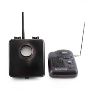
Setup, pairing, and troubleshooting for the MURS-PIR-DRIVEWAY-ALERTS Several Mile Range Driveway Alert.
- Dakota Alert™
- MURS Alert™
- Transmitter
- Long range driveway
- alarm and real time
- trail monitoring system
- Owner's Manual
TABLE OF CONTENTS
Warnings 2 Power Supply 3 Diagrams 3-5 Installation 3-4 Alert Signal 4 Radio location 5 PIR Detection 5 Channel selection 6 Sub-Channel (CTCSS) 6 Zone selection 6 Technical support 6 MURS Frequencies 7 Address 8 Warranty 8 2
WARNINGS
To maintain compliance with the FCC's RF exposure guidelines, this transmitter and its antenna must maintain a separation distance of at least 2 inches (5 centimeters) from your body while transmitting.
This transmitter must have the antenna connected while operating. Failure to connect the antenna can cause damage to the radio.
This device complies with Part 15 of the FCC rules, Operation of this device is subject to the following conditions:
- This device may not cause harmful interference.
- This device must accept any interference, including interference that may cause undesired operation.
Thank you for your purchase of this Dakota Alert product.
The MURS Alert transmitter is a passive infrared (PIR) detector that can be used to detect people, vehicles or large animals at selected locations. The PIR sensor will detect movement of objects up to 80 feet in front of the transmitter box. When a person, vehicle or large animal is detected, the MURS Alert will transmit a signal.
- When an target is detected by the MURS Alert, an alert
- signal will be sent to the M538-HT or M538-BS MURS
- radio. (See page 4 for more information about alerts)
Instructions
When you open the MURS exterior case (figure 1-1), you will see an antenna (figure 1-2), a battery pack and the PIR unit. Attach the antenna to the antenna jack (figure 1-3), located on the top of the case.
Power Supply
The MURS Alert transmitter is powered by 6 AA batteries. For best results, we recommended that you use good quality alkaline batteries. When replacing batteries, do not mix old and new batteries together. The average life of the batteries is about 6 months under normal conditions. Conditions affecting battery life include use of the product in high traffic areas, and using product in a cold climate. If you live in a cold climate, it is recommended that you put in new batteries at the beginning of winter.
MURS Alert Transmitter Antenna
(figure 1)
- Exterior Case
- Antenna
- Antenna jack (exterior) 3.
Installation
- In order for the sensor to detect properly
- it is recommended that the transmitter be
- mounted on a tree or post about 20 feet back
- from the area to be monitored and about 3
- to 4 feet off the ground. If you want to detect
- smaller animals, the sensor can be mounted
- closer to the ground. (See figure 2)
Alert Signal
The MURS alert transmitter has 4 different alert signals. The alert signal will repeat the location of the transmitter. The signal will be a voice saying "Alert zone one...," "Alert zone two...," "Alert zone three...," or "Alert zone four." If you have more than one transmitter, you may wish to change the alert from the default setting (Alert zone one...) to one of the other alerts. This can be done by changing the position of the switch, located on the radio transmitter.
(figure 2)
4.
figure 3 figure 4
- PIR sensor 5. Retention clips 6. Channel switch 7.Sub-channel switch 8.Alert zone message switch Locating the radio transmitter: When looking at the PIR (figure 3) you will see clips on the sides of the plastic case. Push one of the clips away from the center of the case and lift out the PIR and the plastic back-ing. You will now be looking inside of the case at the radio transmitter (figure 4-⑧). To change the settings of the radio transmitter, locate the alert switch. This is a 4 position 5.
slide switch. If the switch is all the way to the top, it will be zone one, the other zones will be located in order from the top.
Operation
A. The factory-set default for the transmitter is Channel 01 Sub-channel (CTCSS) 01. B. Channel selection. The MURS Alert transmitter is capable of transmitting on any of the 5 MURS channels. To select the proper channel, locate SW1 (figure 4-⑥) and set it to the appropriate channel, If SW 1 is set to "0" it will default to channel 1. C. Sub Channel (CTCSS) selection. To select the proper CTCSS locate SW2 and SW3 (figure 4-⑦). SW2 is labeled 0-3, SW3 is labeled 0-9. SW2 represents the first digit in the CTCSS and SW3 represents the second digit in the CTCSS. Example for CTCSS to be set at 38, SW2 must be set at 3 and SW3 must be set at 8. The are 38 different CTCSS combinations, if the CTCSS is set at 39 or 00, no sub code will be in use.
TECHNICAL SUPPORT
If you encounter any difficulty in the operation of this product after reading the manual, please contact us. You can reach us by phone at 605-356-2772 from 8:30 AM to 5:00 PM Monday through Friday (Central Standard Time). We will be happy to answer your questions and help you in any way we can.
6.
Frequency Chart
- | Channel | Channel Type | Frequency (MHz) | Power (Watts) |
- |---|---|---|---|
- | 1 | MURS | 151.820 | 1.1 |
- | 2 | MURS | 151.880 | 1.1 |
- | 3 | MURS | 151.940 | 1.1 |
- | 4 | MURS | 154.570 | 1.1 |
- | 5 | MURS | 154.600 | 1.1 |
Sub Code (CTCSS) Frequency
| Code | Frequency (Hz) | Code | Frequency (Hz) | Code | Frequency (Hz) | |---|---|---|---|---|---| | 00 | 0 | 13 | 103.5 | 26 | 162.2 | | 01 | 67.0 | 14 | 107.2 | 27 | 173.8 | | 02 | 71.9 | 15 | 110.9 | 28 | 179.9 | | 03 | 74.4 | 16 | 114.8 | 29 | 186.2 | | 04 | 77.0 | 17 | 118.8 | 30 | 192.8 | | 05 | 79.7 | 18 | 123.0 | 31 | 203.5 | | 06 | 82.5 | 19 | 127.3 | 32 | 210.7 | | 07 | 85.4 | 20 | 131.8 | 33 | 218.1 | | 08 | 88.5 | 21 | 136.5 | 34 | 210.7 | | 09 | 91.5 | 22 | 141.3 | 35 | 225.7 | | 10 | 94.8 | 23 | 146.2 | 36 | 233.6 | | 11 | 97.4 | 24 | 151.4 | 37 | 241.8 | | 12 | 100 | 25 | 156.7 | 38 | 250.3 |
7.
WARRANTY
Dakota Alert warrants this product to be free of defects in material and workmanship for a period of one year from the date of purchase. This warranty does not cover damage resulting from accident, abuse, act of God or improper operation. If this product does become defective, simply return it to Dakota Alert. Please include a note describing the troubles along with your name and return address as well as the original sales receipt. If the product is covered under warranty it will be repaired or replaced at no charge. If it is not covered by warranty, you will be notified of any charges before work is done.
Please ship to: Dakota Alert, Inc. 109 W. Main St. P0 Box 130 Elk Point, SD 57025 Phone: (605) 356-2772 Fax: (605) 356-2584 Web: www.dakotaalert.com
8.