
Product manual
ERA-PIR-SPK User Manual
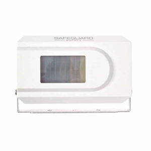
Setup, pairing, and troubleshooting for the ERA-PIR-SPK Motion-Activated Door Alarm with Built In Speaker.
ERA-PIR-SPK Owner’s Manual
Introduction
- The ERA-PIR-SPK is a passive infrared (PIR) sensor with an internal
- speaker that is activated when a combination of heat &
- movement is detected in the monitored zone. When the sensor
- is activated, the internal speaker will play one (1) of three (3)
- different tones. The unit was designed so you can mount the
- bracket on the door frame or wall and easily pivot the lens to
optimize the desired monitored zone. Helpful Tips:
- Do not mount the speaker to the wall or door frame until you have successfully setup and tested the device.
Volume Control
4 levels & set to highest volume level at the factory.
- Each unit is programmed to the "ding-dong" sound from the factory. User may change this melody.
- If you are happy with the preset volume & tone, you can skip the step titled "Setting the Tone and Setting Volume Level" section of this manual.
- When battery is low a special tone is emitted. See "Note" in
Battery Installation
section of manual below.
- The unit resets every 5 seconds after each activation. ERA-PIR-SPK Battery Installation: The sensor is powered by a 9V alkaline battery. Follow the steps below to remove the cover and install the battery. Note: Program the tone and volume level prior to reassembling the unit. 1. Remove the screw located on the backside of the case using a phillips head screwdriver (see figure 1). Once the screw is removed, open the case. 2. Remove top half of case from lower half of the case to find the battery holder (see figure 2). 3. Install a fresh 9-volt alkaline battery. 4. Follow the instructions for "Setting the Tone and Volume Level" prior to reassembly. figure 1. Note: When motion is detected & the battery is weak, 2 seconds after the alert tone plays, the unit will emit a "Beep Beep" every 5 seconds, repeating 5 times. This is notice that the battery should be changed. figure 2. Setting the Tone and Setting Volume Level Setting the Tone: By default, each zone is programmed by the factory to play the ding-dong sound at the highest volume level. You can skip this step if you are OK with this tone and volume level. 1. Hold down the "volume control and tone selector" button for approximately 3 seconds until the RED LED on the board is lighted (see figure 2). The solid red light lets you know the unit is in program mode. When the LED is red, release the button. 2. Press the "volume control and tone selector" button to scroll through the 3 available tones, stopping at the one you like. 3. Hold down the "
Volume Control
- and tone selector" button
- until the red LED goes off. No red LED means the unit IS NOT
- in programming mode.
- Note: Unit will exit programming mode automatically after 5
seconds with no activity.
--- page break ---
Volume Adjustment:
- The volume is also controlled by the "volume control and
- tone selector button." To change the volume level, make
- sure the unit is not in program mode. Ensure the RED LED IS
- NOT lighted (Lighted RED LED means the unit is in
- programming mode.)
- 1. The sensor has four volume levels. By default the unit is set
- to volume 4, the highest volume level.
- 2. To adjust the volume, press the "volume control and tone
- selector" button until the desired volume level is reached
(see figure 2). 3. After adjusting the volume, reassemble the unit.
Mounting
- The PIR sensor (transmitter) may be mounted in a variety of locations such as; on the ceiling, directly above the door, or side mounted. The most common mounting location is above the door.
- For best results, mount the transmitter above the door frame slightly canted in towards the door. You may cant (tilt) the unit to ensure the monitored zone is covering the area you want it to cover.
- Avoid placing the transmitter near heating & A/C ducts, or in direct sunlight to help eliminate false signals.
- The mounting height of the sensor (see table 1) changes the size of the monitored zone. Height Width Depth 8’ 9.20’ 0.60’ 10’ 11.5’ 0.75’ 13’ 14.95’ 0.98’ Table 1 16’ 18.40’ 1.20’ *Height of Sensor (in feet) Changes the Width and Depth of Monitored Zone. 1. Use included screw to mount the metallic bracket. We recommend mounting the bracket so that the openings on each end of the bracket are facing up (shaped liked a "U"). 2. Each side of the transmitter has a screw protruding. That screw slides into the u-shaped openings of the bracket. 3. Insert the unit into the bracket. Each screw on the sides of the sensor should rest on open ends of the u-shaped bracket. 4. Tighten the screws on the side of the case just enough to keep it in place (do not let it fall out). 5. Tilt sensor in bracket to create desired monitored zone and test. 6. Tighten the screws on each side of the case to secure it to the bracket. TECHNICAL SUPPORT If you encounter any difficulty in the operation of this product after reading the manual, please contact us. You can reach us by phone at 904-245-1184 from 8:00 AM to 5:00 PM Monday through Friday (Eastern Standard Time). We will be happy to answer your questions and help you in any way we can.
Warranty
- Safeguard Supply warrants this product to be free of defects in material and
- workmanship for a period of one year from the date of purchase. This warranty
- does not cover damage resulting from accident, abuse, act of God or improper
- operation. If this product does become defective, simply return it to Safeguard
- Supply. Please include a note describing the troubles along with your name and
- return address as well as the original sales receipt. If the product is covered under
- warranty it will be repaired or replaced at no charge. If it is not covered by
- warranty, you will be notified of any charges before work is done.
- Safeguard Supply - www.safeguardsupply.com
- 2260 Moon Station Ct. NW #110 , Kennesaw, GA 30144
- Phone: (678) 214-4212
- WARNING: Cancer and Reproductive Harm. Go to www.P65Warnings.ca.gov
for more information.