
MAPS User Manual
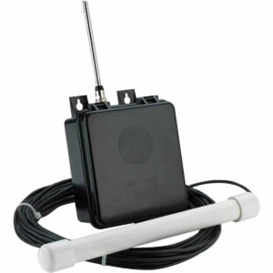
Setup, pairing, and troubleshooting for the MAPS Dakota Alert Driveway Alert Probe -Several Mile Range.
MURS Alert Probe
WARNINGS
To maintain compliance with the FCC's RF exposure guidelines, this transmitter and its antenna must maintain a separation distance of at least 2 inches (5 centimeters) from your body while transmitting.
This transmitter must have the antenna connected while operating. Failure to connect the antenna can cause damage to the radio.
This device complies with Part 15 of the FCC rules, Operation of this device is subject to the following conditions: 1. This device may not cause harmful interference. 2. This device must accept any interference, including interference that may cause undesired operation.
CONTENTS
MURS Alert probe transmitter Antenna
DIAGRAM
- Exterior Case (figure 1)
- Probe sensor control (figure 2)
- MURS transmitter (figure 2)
- Switch (SW1) (figure 2)
- Switch (SW2) (figure 2)
- Switch (SW3) (figure 2)
- Switch (SW4) (figure 2)
- Antenna (figure 1)
- Antenna connector (figure 1)
- Exterior Case
- (Figure 1)
- (Figure 2)
Power Supply
The MURS Alert probe transmitter is powered by 6 AA batteries. It is recommended that you use good quality alkaline batteries. When changing the batteries, do not mix old and new batteries together. The life of the batteries should be about 6 months under normal conditions. In high traffic areas, the batteries will go down sooner. Also, in a cold climate it is recommended that you put fresh batteries in about the beginning of winter.
Function
A. Detection. The MURS Alert probe transmitter is a metal detector that can be used to detect vehicles. The probe sensor will detect movement of vehicles about 14 feet either side of the probe. When a vehicle is detected, the MURS Alert will transmit a signal. B. In order for the sensor to detect properly it is recommended that the probe be buried along side the drive and the transmitter box mounted on a tree or post nearby. If you have a very wide driveway, you may need to bury the probe in the center of the drive. If you do this, place the probe and wire in a 2 inch schedule 80 PVC pipe and bury it at least a foot deep. This is done to protect the probe and wire from any damage. It is also prudent to place the wire in a conduit to protect it from inadvertent damage from rodents or future digging projects. C. Alert Signal. When an target is detected by the MURS Alert, an alert signal will be sent to the M538-HT or M538-BS MURS radio. There are 4 different Alert signals that can be sent. The alert signal will repeat the location of the transmitter. The signal will be “Alert Zone One,...”, “Alert Zone Two,...”, “Alert Zone Three,...” or “Alert Zone Four,...” D. To locate the radio transmitter, you will need to open the front cover exterior case. . You will now see the radio transmitter (figure 2). To change the settings of the radio transmitter, please go through the procedure in the next section. E. The gray knob on the lower right area of the PCB is the sensitivity control. This can be used top increase or decrease the sensitivity of the probe. In most locations the sensitivity should be set at the mid point (12 o’clock). Rotate the knob clockwise to increase sensitivity. Note, do not operate with the sensitivity knob fully clockwise, as false signals may result. Move the knob slightly off the fully clockwise stop.
Operation
A. Channel selection. The MURS Alert transmitter is capable of transmitting on any of the 5 MURS channels. To select the proper channel, locate SW1 (figure 2) and set it to the appropriate channel. If SW 1 is set to “0” it will default to channel 1. B. Sub Channel (CTCSS) selection. To select the proper CTCSS locate SW2 and SW3 (figure 2). SW2 is labeled 0-3, SW3 is labeled 0-9. SW2 represents the first digit in the CTCSS and SW3 represents the second digit in the CTCSS. Example for CTCSS to be set at 38, SW2 must be set at 3 and SW3 must be set at 8. The
are 38 different CTCSS combinations, if the CTCSS is set at 39 or 00, no sub code will be in use. C. Alert signal. You can select one of four different alert signals, Alert Zone One, Alert Zone Two, Alert Zone Three, or Alert Zone Four. To select the Alert signal, locate SW 4 (figure 2). This is a 4 position slide switch. If the switch is all the way to the top, it will be zone one, the other zones will be located in order from the top.
MURS Frequencies
- Channel Frequency
- 1 151.820MHz
- 2 151.880MHz
- 3 151.940MHz
- 4 154.570MHz
- 5 154.600MHz
TECHNICAL SUPPORT
Thank you for your purchase of the Dakota Alert product.
If you encounter any difficulty in the operation of this product after reading the manual, please contact us. You can reach us by phone at 605-356-2772 from 8:30 AM to 5:00 PM Monday through Friday (Central Standard Time). We will be happy to answer your questions and help you in any way we can.
WARRANTY
Dakota Alert warrants this product to be free of defects in material and workmanship for a period of one year from the date of purchase. This warranty does not cover damage resulting from accident, abuse, act of God or improper operation.
If this product does become defective, simply return it to Dakota Alert. Please include a note describing the troubles along with your name and return address as well as the original sales receipt. If the product is covered under warranty it will be repaired or replaced at no charge. If it is not covered by warranty, you will be notified of any charges before work is done.
Please ship to: Dakota Alert, Inc. 109 W. Main St. PO Box 130 Elk Point, SD 57025