
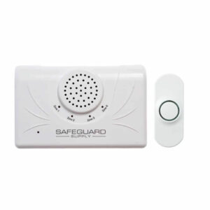
ERA-PBDCR User Manual
Setup, pairing, and troubleshooting for the ERA-PBDCR Commercial Door Chime Kit w/ 4,000 Range.
&3" 1#%$3
- Owner’s Manual
- This device complies with Part 15 of the FCC rules, Operation of this device is subject
- to the following conditions: 1. This device may not cause harmful interference. 2. This
- device must accept any interference, including interference that may cause unde-
- sired operation.
- )eMQGVM /oteT
- Each receiver is capable of pairing with four (4) transmitters per zone.
- Each zone features 1 x 127 D$ output.
- 0utput duration for the 127 D$ output may be set to 5 sec, 1 sec, 1 min, & 2 min. The receiver features 1 x $ Form relay assignable to one or multiple zones & will taLe on the duration of the 127 D$ output.
- 7olume control 4 levels plus mute, plus off.
- Each transmitter must be paired to a zone on the receiver.
- Each zone is programmed to the "ding dong" sound from the factory. 6ser may change this melody.
- 8hen transmitter battery is low, it sends a signal to the receiver when triggered & the corresponding LED on the receiver will continue to flash for 1 minutes.
- The E3A 1#T9 is a push button transmitter that must be programmed to a E3A compatible receiver to operated.
- 1ush button measures 3. hh H x 2.25hh 8 x 1. 5hh D.
- The halo ring around the center push will illuminate dimly for visibility at night (this feature consumes very little power.)
- 8hen triggered (center push button is pressed) the center halo illuminates brightly for approximately 2 seconds.
- The push button is outdoor rated and contains a silicone gasLet to Leep moisture out. .ount with the small weep hole pointing down to ensure any moisture in the unit evaporates out. Battery InTtaMMation 1. 0pen the front cover by inserting the included screwdriver into the sRuare hole on the bottom of the unit (figure 1) & gently push & then separate the top & bottom halves of the case. 2. 3emove top part of case from lower part of case (figure 2). 3. *nstall the included $3245 A battery into the holder with positive ( ) side of the battery facing up (figure 2). 4. Test the battery by pressing the center push. The green halo should illuminate for approximately 2 seconds, signaling transmission. /ote 1rogram the push button to a compatible receiver 13*03 to mounting the push button. 1air 5ranTNitter to 3eceiWer (Always test unit prior to installation) The transmitter worLs with the E3A D$39 receiver & basic programming calls for the user to pair the transmitters with a receiver & select a melody for the transmitter to instruct the receiver to play when triggered. For quick setup, however, each zone defaults to a basic "ding-dong" sound allowing you to easily
Pairing the Transmitter
for a faster set up process.
- 1. 0n the E3A D$39 receiver, hold down the "mode" (left button in figure 3
- below) button until you hear a short tone sound & the "zone 1" LED flashes
- (approx 3 sec).
- 2. *f you are programming the transmitter to zone 1 press the button on your
- transmitter. :ou will hear the receiver play a short musical note (zone 1 will
- continue to flash).
- 3. To program a transmitter to a different zone, press the "zone" button on
- the receiver to scroll to the appropriate zone . The zone you want to
program will flash. 3epeat step 2 above. 4. 0nce you have programmed all the zones move to the next step. 5. To exit program mode, hold down the "mode" button until you hear a short tone sound (approx 3 sec)
- $hanHinH the ;one .eMody
- By default, each zone is programmed by the factory to play the ding-dong
- sound
- 1. Hold down the "zone" button until you hear a short tone & all LEDs on
- front panel of receiver are red (approx 3 seconds). The zone you are
- programming will flash.
- 2. 1ress the "volume" button to scroll through the 12 available melodies
- for selection. 0nce you find a melody you liLe, move to step 3.
- 3. 1ress the "zone" button to scroll to the next zone & repeat step 2 to
- program a melody to other zones.
- 4. 0nce you have programmed a melody to all necessary zones, move to
- step 5.
- 5. Hold down the "zone" button until you hear a short tone sound (approx
- 3 seconds) notifying the receiver is out of melody programming mode.
- 7oMVNe .Vte 0GG
- The volume button on the side of the receiver controls the four different volume
- levels, mutes & turns off the receiver. Pushing the volume button controls these
functions.
- 8hen all four zone LED lights are red, this indicates maximum volume.
- Three zone LED lights indicate the third volume level.
- Two zone LED lights indicate the second volume level.
- 0ne zone LED light indicates the minimum volume level.
- /o zone LED lights & a red power indicator light means the --- page break --- Low Battery Indicator 8hen the battery in the E3A 1#T9 is low & needs to be replaced, it will signal the receiver to double play the programmed melody on the receiver when triggered. For example, if you have programmed the "ding dong" sound for the push button to play on the receiver, when the battery on the push button is low, the receiver will play "ding dong...ding dong" when triggered, notifying you to change the battery in the push button. &raTinH 1roHraNNinH NeNory 1. Hold down "mode" button until you hear a short tone & the zone 1 LED flashes. 2. Hold down the "mode" & "volume" button simultaneously until all LEDs stop flashing & you hear a short melody sound (approximately 5 seconds). 3. All LEDs will stop flashing & only the green LED power indicator will display. The memory is now erased. 6TinH 7 %$ 0VtQVtT
- Each zone on the E3A D$39 features a live 127 D$ output.
- The output duration may be set to 5 seconds, 1 seconds, 1 minute or 2 minutes using the dip switches located inside the receiver.
- The output duration settings will apply to all zones & the $ Form 3elay.
- The $ Form 3elay may be associated with a specific zone or multiple zones.
- 127 D$ output current 4 mA maximum. $onnectinH a 7 %$ %eWice 6nplug the receiver. Separate top receiver case from bottom receiver case. Locate terminal blocL (see figure 4) located on the bottom of the pc board. Loosen screws for the zone(s) that you are connecting a device to. 8ire the external 127 D$ into the terminal connection blocLs that corresponds to the respective zone. For example, if a push button is paired to zone 1, and you want a strobe to flash for zone 1, wire the strobe into the terminal block for zone 1. 0bserve polarity when necessary. For example, for a strobe light, ensure you are connecting the positive wire on the strobe to the positive terminal on the receiver. 3e tighten screws on terminal blocL. Adjust output duration as needed (figure 5) Snap cover bacL together. 1lug in receiver. (Figure 5) (Figure 4) .oVntinH the 1VTh BVtton Ensure you have programmed & tested the push button prior to mounting. There are two
Mounting
- for the E3A 1#T9. The first method is to
- mount the unit using the supplied screws. The second is using the
- supplied double sided tape.
- 1. 0pen the front cover by inserting the included screwdriver into the
- sRuare hole on the bottom of the unit (figure 1 above) & gently push in
to separate the top & bottom half of the case. 2. 3emove top half of case from lower half of case. 3. 1lace bacL cover of push button on wall where you want to mount it. The bacL cover may be mounted using the supplied screws or double sided mountin gtape. 4. Ensure the arrow inside the bacL cover is pointing up. 5. .ount bacL half of case on wall.
- . 1lace top half (with battery installed) over bottom half. .aLe sure the
- small opening (see figure 1 above)on top half is pointing down. 1lace
- bottom of the top half over the small protruding clip on bottom half &
- snap into place.
- TECHNICAL SUPPORT
- If you encounter any difficulty in the operation of this product after reading
- the manual, please contact us. You can reach us by phone at 4 245 11 4
- from 8: 0 AM to 5:00 PM Monday through Friday (Eastern Standard Time). We
will be happy to answer your questions and help you in any way we can.
Warranty
- Safeguard Supply warrants this product to be free of defects in material and
- workmanship for a period of one year from the date of purchase. This
- warranty does not cover damage resulting from accident, abuse, act of God
- or improper operation. If this product does become defective, simply return
- it to Safeguard Supply. Please include a note describing the troubles along
- with your name and return address as well as the original sales receipt. If the
- product is covered under warranty it will be repaired or replaced at no
- charge. If it is not covered by warranty, you will be notified of any charges
- before work is done.
- Safeguard Supply
- 22 .oon Station $t. /8 11
- Kennesaw, (A 3 144
www.safeguardsupply.com