
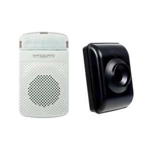
ERA-DSRXPG User Manual
Setup, pairing, and troubleshooting for the ERA-DSRXPG - 4,000ft Driveway Alarm Kit: Flashing Strobe Receiver.
- &RA-DSRXPG Alarm Kit
- Owner’s Manual
- 5IJT EFWJDF DPNQMJFT XJUI 1BSU PG UIF '$$ SVMFT 0QFSBUJPO PG UIJT EFWJDF JT TVCKFDU
- UP UIF GPMMPXJOH DPOEJUJPOT 5IJT EFWJDF NBZ OPU DBVTF IBSNGVM JOUFSGFSFODF 5IJT
- EFWJDF NVTU BDDFQU BOZ JOUFSGFSFODF JODMVEJOH JOUFSGFSFODF UIBU NBZ DBVTF VOEF
- TJSFE PQFSBUJPO
Introduction
- The ERA-DSTX is an outdoor rated P*R sensor compatible with all ERA
- receivers. 8hen the combination of heat motion are detected, the
- sensor will transmit a wireless radio signal up to , ft. to the receiver .
- This user manual is for the ERA-DSRXPG which includes one outdoor
- driveway sensor one plugin receiver.
- )elQGul /oteT
- The ERA-DSTX must be programmed to a ERA receiver to function.
Programming
instructions, settings, mounting instructions are included in this manual.
- $onsult the receiverhs user manual for more details
Specifications
for settings.
- The ERA-DSTX is powered by a 7 alLaline battery (not included).
- 6p to ERA-DSTXhs may be programmed to a ERA receiver, Therehs no limit to the number of receivers programmed to the ERA-DSTX.
- *ths recommended to choose a different melody for each programmed receiver so you can determine which transmitter triggered the receiver.
- 8hen the transmitter battery is low, it cause the receiver to generate the sound twice in a row.
- PacLage contents P*R sensor transmitter, plate mount, swivel mount, screws ( ), plugin receiver, this user guide. ERA-DSTX Sensor Specifications:
- Power source: 9V alkaline battery
- Detection range low, to 5 ft., medium, to 5 ft., high, to ft.
- 8ireless range up to , ft.
Dimensions
(HY8YD) .5 Y Y . 5 inches
- Operating temperature - to ' (- . to . $)
- Operating freRuency .H[ SetuQ SteQT Gor Setting 6Q SenTor 5ranTNitter . *nstall a 7 battery (not included). See the section titled "Battery *nstallation." /ote do not re-assmeble the case until programming is complete. . Pair the sensor transmitter to the receiver. See section titled Pair 5ranTNitter to 3eceiWer Once you have . /ote some settings of the transmitter may be adKusted as needed. Please see section titled "EWanceE SenTor SettingT
Battery Installation
. Remove the four screws on the bacL of the sensor/transmitter case using a Phillips head screwdriver (figure ). . Remove top half of case from lower case. . *nstall a 7 alLaline battery place it in the holder (figure ).
- . See section titled, "Pairing 5ranTNitter to 3eceiWer
- 5. /ote 8hen battery gets weaL, it will cause paired [one to flash LED on
- receiver for minutes when triggered.
- ('igure )
- ('igure )
- Pair 5ranTNitter to 3eceiWer
- (Always test unit prior to installation)
- The transmitter worLs with the included receiver, the ERA-RXPG, as well as the
- ERA-D$RX ERA-7PRX receivers. Basic programming calls for the user to pair
- the transmitters with a receiver select a melody for the transmitter to
- instruct the receiver to play when triggered.
- 'PS RVJDL TFUVQ IPXFWFS FBDI [POF EFGBVMUT UP B CBTJD EJOH EPOH
- TPVOE BMMPXJOH ZPV UP FBTJMZ QBJS UIF USBOTNJUUFS GPS B GBTUFS TFU VQ QSPDFTT
- 1. Plugin the receiver (figure 5) into a standard wall outlet.
- 2. Hold down the "mode" button on the receiver until you hear a short tone
- sound. A red LED will appear in the strobe lens of the receiver. This
- denotes programming mode.
- 3. By default, the receiver is set to play the "ding-dong" sound. To change
- the melody, press the "volume" button to scroll through the available
- sounds. Once you hear the melody want, stop pressing the button.
- 4. Next wave your hand over the "sensor cell" or press the "test" button on
- the transmitter/sensor (see figure 4).
- 5. You should hear a quick chime sound denoting successful pairing of the
- sensor to the receiver. If this is the only sensor/transmitter you are
- programming, go to the next step. To pair an additional transmitter,
- repeat steps 3 & 4.
- 6. To exit programming mode, hold down the "mode" button (figure 5)
- until you hear a short tone sound (approximately 3 seconds).
- ('igure 5)
- ('igure )
--- page break ---
"EWanceE SenTor 5ranTNitter SettingT Note:
- Remove the battery. Prior to adKusting any sensor settings, please remove the battery. Remove bacL cover and disconnect the battery. See "BatterZ *nTtallation
- Remove adKust Kumper. +umpers are small blacL plastic pieces that fit over pins on the circuit board. (figure 5). ('igure 5)
- Gently slide the Kumper off the pins for the settings you would liLe to change. *f you cannot use your fingers, you can use twee[ers.
- Slide the Kumper bacL onto the pair of Kumper pins that correspond with the setting you want to change (see images below).
- 3ange $hanges the distance that the motion detector will detect motion (si[e of monitored [one).
- -&% Turn LED on off (LED triggered when unit is transmitting radio signal).
- 'ilter $hanges the sensitivity level of the motion detector. Recommended O'' for indoor use, O/ for outdoor use).
- 3eTet $hanged minimum time between alarm activations. Mounting tIe 5ranTNitter Note: 5P HFU UIF NBYJNVN QPTTJCMF SBOHF NPVOU UIF USBOTNJUUFS TFOTPS PO B XPPEFO PS QMBTUJD PCKFDU JG QPTTJCMF GSFF GSPN PCTUBDMFT 5IF SBOHF JT VQ UP GU CVU FOWJSPONFOUBM GBDUPST NBZ SFEVDF UIJT SBOHF
- -ocation o Try to mount on a wooden post, fence or tree. Avoid mounting on metal if possible. o Try to mount in a location free of obstacles such as metal siding, trees that may cause transmission interfence. o The product has a very long range, but these obstacles will interfere in the effective range. o Try to place unit - ft. off the ground approYimately ft. from either side of driveway or path you are monitoring. o The sensor will detect people vehicles up to approYimately ft. away (on high setting), sometimes even farther. 'or this reason, avoid pointing the transmitter sensor at roads in the distance. o .aLe sure unit is mounted so that it does not move during wind or storms. This could generate false triggers.
- Select a Mounting Bracket o Plate mount is ideal for outdoor locations (trees, posts, fence). See figure . o Swivel mount is ideal for indoor locations (figure ). (Figure 6)
- Select a Mounting Bracket o Ensure arrow on bracLet is facing up. o Slide transmitter down on bracLet. LED on transmitter should be towards the top of the case to function correctly. (figure ). ('igure ) TECHNICAL SUPPORT *f you encounter any difficulty in the operation of this product after reading the manual, please contact us. :ou can reach us by phone at - 5- from A. to 5 P. .onday through 'riday (Eastern Standard Time). 8e will be happy to answer your Ruestions and help you in any way we can.
Warranty
Safeguard Supply warrants this product to be free of defects in material and worLmanship for a period of one year from the date of purchase. This warranty does not cover damage resulting from accident, abuse, act of god or improper operation. *f this product does become defective, simply return it to Safeguard Supply. Please include a note describing the troubles along with your name and return address as well as the original sales receipt. *f the product is covered under warranty it will be repaired or replaced at no charge. *f it is not covered by
- warranty, you will be notified of any charges
- before worL is done.
- Safeguard Supply
- .oon Station $t. /8
- ,ennesaw, GA
www.safeguardsupply.com