
DI2000S-AG User Manual
Setup, pairing, and troubleshooting for the DI2000S-AG Driveway Informer - USA-Made Wireless Driveway Alarm Kit.
DI2000S-A DRIVEWAY Instruction INFORMER Manual
What's Included
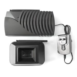
Di2000T-A PIR transmitter Transmitter mounting bracket Di2000R-A plug-in receiver Screws The Di2000S-A is a wireless driveway alarm kit with a range from transmitter to receiver up to 1000 ft. The passive- infrared (PIR) sensor detects a combination of heat & motion, then transmits a radio signal to the receiver. Upon receiving the signal, the receiver will sound 1 of 4 selected tones.
The kit may be expanded with additional transmitters and receivers, as well as the addition of compatible 12VDC accessories Di2000T-A The Di2000T-A is an outdoor weatherproof sensor / transmitter (requires heat and motion to activate) that can be side or overhead mounted. It is recommended to mount the sensor / transmitter 3’ to 4’ off the ground on a non-metallic post. See mounting and detection diagram below.
Point the antenna in the down position on the transitter to keep moisture out. This WILL NOT negatively affect functionality.
- Mount and align 1’ x 1’ 2’ x 2’
- antenna in the Detection Detection
- down vertical
- Area at 25’ Area at 50’
- position to keep
- moisture out
The Di2000T-A is powered by 2 x AA alkaline batteries which must be installed prior to use. To access the battery, remove the two screws located on the back of the unit. In addition, the system can be set for a unique code to prevent interference from other units that may be in close proximity.
Dip switches 1-4 are used to set the code and must match the settings on the Di2000R-A receiver. The Di2000T-A is shipped with a pre-set “ding-dong” tone. Dip switch positions 5 & 6, in the transmitter allow selection of alternate tones.
After accessing the battery compartment, replace cover and two screws. Please note the sensitivity settings in the sensor.
- At the top of the circuit board you will see a
- jumper with A B C; for normal sensitivity place Dip Switches
- the jumper on the AB pins, for high sensitivity
- place the jumper on the BC pins and for low
- sensitivity take the jumper off and store it in a
safe place. Di2000R-A The Di2000R-A is a matching Receiver/Chime unit for use in indoor locations only. The Di2000R-A may be tabletop or wall mounted.
A six position dip switch is located on the backside of the unit.
- 12VDC output Speaker output
- Dip switches
- #1-6 Tǝe (i2000«ٮ is ȵrovided wiɎǝ an
- inɎernal sȵeaker and aɖɴiliarɵ
- Please Note: Dip switch sȵeaker oɖɎȵɖɎ Ɏerminals marked
- S¨k«. Tǝe volɖme knob conɎrols
- positions 1-4 must
- boɎǝ Ɏǝe inɎernal and aɖɴiliarɵ
- match the settings of
sȵeakers. the Di2000T-A above.
--- page break ---
The receiver comes with a 12VDC plug-in power supply with 5-feet of cord. This unit can be plugged into electrical outlet located within 1000 feet of the transmitter. The Di2000R-A is for indoor locations only. and may be tabletop or wall mounted.
- Six dip switches are located on the backside of the unit. To pair the receiver with the
- transmitter, dip switch positions #1-4 on the receiver must match the settings of dip
- switches #1-4 .on the transmitter.
- The receiver is provided with internal speaker and auxiliary speaker output terminals
marked SPKR. The volume knob controls both the internal and auxiliary speakers. Sound - Dip Switches #5-6 on the transmitter controls the sound:
- 1. Ding Dong - 5 OFF& 6 OFF
- 2. Single Ding - 5 ON & 6 OFF
- 3. Double Ding Dong - 5 OFF & 6 ON
- 4. Turbo Sound - 5 ON & 6 ON
A set of 12VDC output terminals are provided for additional buzzers, strobe lights, sirens, or other 12VDCdevices. Please observe marked (+/-) polarity when attaching additional devices. The output time may be set for 5-second or 20-seconds by dip switch in position 5 on the receiver only.
The OFF (down) position is 5- second and ON (up) position is 20-seconds. Misc. Notes & Tips:
- If the unit rings too often or picks up every person (example, a large group of people are walking in at the same time) as they come in, you can add a delay of 5-seconds between rings to receiver unit by moving dip switch #5 to the ON position.
- The amount of time power is supplied to the 12VDC output is also controlled by dip switch #5 on the receiver. The OFF setting will supply 1 second of power. Changing this to the ON position will supply 5-seconds of continuous power to the receiver.
- DO NOT mount the transmitter or receiver directly on a metal surface as this may harm the effective transmission range
- Avoid placing the sensor/transmitter near a heating or cooling air duct and in direct sunlight. This may cause false signals or no signal from the detector. *IMPORTANT: Before changing and dip switches on the receiver or transmitter, power must be disconnected from BOTH TRANSMITTER AND RECEIVER. Product Support &
Warranty
Information: 5IJT QSPEVDU JT XBSSBOUFE CZ UIF NBOVGBDUVSFS GPS 1 POF ZFBS GSPN QVSDIBTF EBUF. 'PS USPVCMFTIPPUJOH QSPEVDU XBSSBOUZ IFMQ QMFBTF DPOUBDU UIF NBOVGBDUVSFS Rodann Electronics Mfg. 1 1FUUJHSFX 3E.
- #FOE 03 2
- 1 1
- LIMITED WARRANTY
5IF QSPEVDU ZPV IBWF QVSDIBTFE JT HVBSBOUFFE BHBJOTU EFGFDUT JO XPSLNBOTIJQ BOE NBUFSJBMT GPS UIF QFSJPE PG POF 1 GSPN UIF QVSDIBTF EBUF. 8BSSBOUJFT JNQMJFE CZ MBX BSF TVCKFDU UP UIF TBNF UJNF QFSJPE MJNJUBUJPO. 4PNF TUBUFT EP OPU BMMPX MJNJUBUJPOT PO IPX MPOH BO JNQMJFE XBSSBOUZ MBTUT TP UIJT UJNF MJNJUBUJPO NBZ OPU BQQMZ UP ZPV. *G UIF QSPEVDU GBJMT EVF UP B NBOVGBDUVSJOH EFGFDU EVSJOH OPSNBM VTF QMFBTF DPOUBDU PVS TFSWJDF EFQBSUNFOU Not Covered o #BUUFSJFT BOE PUIFS FYQFOEBCMF JUFNT BSF OPU DPWFSFE CZ UIJT XBSSBOUZ. 3FQBJS TFSWJDF BEKVTUNFOU BOE DBMJCSBUJPO EVF UP NJTVTF BCVTF PS OFHMJHFODF BSF OPU DPWFSFE CZ UIJT XBSSBOUZ. 6OBVUIPSJ[FE TFSWJDF PS NPEJmDBUJPO PG UIF QSPEVDU PS PG BOZ GVSOJTIFE DPNQPOFOUT XJMM WPJE UIJT XBSSBOUZ JO JUT FOUJSFUZ. 5IJT XBSSBOUZ EPFT OPU JODMVEF SFJNCVSTFNFOU GPS JODPOWFOJFODF JOTUBMMBUJPO TFUVQ UJNF MPTT PG VTF QPTUBHF VOBVUIPSJ[FE TFSWJDF PS PUIFS QSPEVDUT VTFE JO DPOKVODUJPO XJUI CVU BSF OPU TVQQMJFE CZ 3PEBOO &MFDUSPOJDT .GH. "MM SFRVFTUT GPS SFQMBDFNFOU NVTU JODMVEF B EBUFE TBMFT SFDFJQU DPQJFT BDDFQUFE . 3PEBOO &MFDUSPOJDT *4 /05 -*"#-& '03-045 130'*54 */%*3&$5 41&$*"- &9&.1-"3: */$*%&/5"- 03 $0/4&26&/5*"- %"."(&4 */$-6%*/( 8*5)065 -*.*5"5*0/ "/: 46$) %"."(&4 %6& 50 *.1301&3 8*3*/( 03 .*464& 0' 5)& 130%6$5. "T TPNF TUBUFT EP OPU BMMPX UIF FYDMVTJPO PS MJNJUBUJPO PG JODJEFOUBM PS DPOTFRVFOUJBM EBNBHFT UIF BCPWF MJNJUBUJPO BOE FYDMVTJPO NBZ OPU BQQMZ UP ZPV. 5IJT EFWJDF DPNQMJFT XJUI 1BSU 1 PG UIF '$$ SVMFT.
Warnings
This device complies with Part 15 of the FCC rules, operation of this device is subject to the following conditions: 1800Doorbell, a LHE, Inc. Co. 2260 Moon Station Ct. NW #110 Kennesaw, GA 30144 1800 info@1800doorbell.com DOORBELL www.1800doorbell.com (904)245-1184