
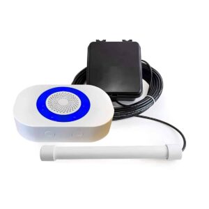
DCPA-4K-PLUS User Manual
Setup, pairing, and troubleshooting for the DCPA-4K-PLUS Dakota Alert Driveway Alarm Only Detects Cars.
Wireless Receiver RE-4k Plus USER GUIDE www.dakotaalert.com TM Dakota Alert® WIRELESS SECURITY EQUIPMENT
--- page break ---
OVERVIEW Terminals Speaker Volume button 2 Bottom Power adapter jack Front LEDs
- Mode button
- Back
- DIP switches
- Mounting holes
--- page break ---
What's Included
- RE-4k Plus receiver
- Power adapter
- User Guide POWERING YOUR RECEIVER 1. Connect the power adapter to the jack in the bottom of the receiver. 2. Plug the power adapter into an AC outlet. Power adapter Bottom 3 --- page break --- SETTING UP YOUR RECEIVER “Basic Setup” lets you choose the tune and LED settings you want for Dakota Alert 4000 Series transmitters. In addition to tune and LED settings, “Advanced Setup” lets you set up exterior sensors using the Relay 1, Relay 2, and the 12 VDC terminals. BASIC SETUP Note: You can connect up to 16 Dakota Alert 4000 Series transmitters to your receiver. 1. Place your receiver and transmitter(s) next to each other. Note: Be careful not to activate your transmitter until you select the tune you want. If you do accidentally activate the transmitter on the wrong tune, reselect a tune and reactivate the transmitter. 2. Press and hold the MODE button for three seconds until all LEDs flash and start blinking slowly. 3. Press the (volume) button repeatedly until you find the tune you want to sound when a transmitter is activated. 1 Ding Dong (high) 5 Alarm/Siren 9 William Tell 13 Beep (high) 2 Ding Dong (low) 6 Coo Coo Clock 10 Canon in D 14 Beep (low) 3 Westminster 7 Bird Chirping 11 Morning 15 Beep, Beep 4 Fur Elise 8 Twinkle 12 Toreador 16 Beep, Beep, Twinkle March Beep, Beep 4 --- page break --- 4. After you choose a tune, activate the transmitter (for example, press its button or wave your hand over its motion sensor). The receiver emits a short beep to confirm the transmitter has been coded. Note: If you accidentally activate the transmitter on the wrong tune, press the (volume) button to reselect a tune and reactivate the transmitter. 5. If you are coding more than one transmitter, repeat steps 3–4. 6. After your transmitter(s) are coded, press and hold the MODE button until the LEDs stop flashing. 7. To test the transmitter tune, activate the transmitter. You’ll hear the selected tune through your receiver and the LEDs will flash. 5 --- page break --- ADVANCED SETUP Note: You can connect up to 16 Dakota Alert 4000 Series transmitters to your receiver. Each transmitter can be set to independently sound a tune, flash the LED, or control the 12VDC output and relay outputs for the selected time. 1. Place your receiver and transmitter(s) next to each other. Note: Be careful not to activate your transmitter until you select the tune you want. If you do accidentally activate the transmitter on the wrong tune, reselect a tune and reactivate the transmitter. 2. Press and hold the MODE button for three seconds until all LEDs flash and start blinking slowly. 3. Set the DIP switches to control the actions when a signal is received: DIP 1: LEDs flash – on or off DIP 2: Chime or tune – on or off DIP 3: Relay 1 output – on or off DIP 4: Relay 2 output – on or off DIP 5: 12VDC output – on or off On DIP 6 & 7: Control the time duration for the Relay 1, Relay 2, or 12 VDC terminals: Off DIP 6 “Off ” and DIP 7 “Off ”: 1 second DIP 6 “On” and DIP 7 “Off ”: 5 seconds DIP 6 “Off ” and DIP 7 “On”: 15 seconds DIP 6 “On” and DIP 7 “On”: 5 minutes 6 --- page break --- 4. Press the (volume) button repeatedly until you find the tune you want to sound when a transmitter is activated. 1 Ding Dong (high) 5 Alarm/Siren 9 William Tell 13 Beep (high) 2 Ding Dong (low) 6 Coo Coo Clock 10 Canon in D 14 Beep (low) 3 Westminster 7 Bird Chirping 11 Morning 15 Beep, Beep 4 Fur Elise 8 Twinkle 12 Toreador 16 Beep, Beep, Twinkle March Beep, Beep 5. After you choose a tune and set the DIP switches to control the outputs, activate the transmitter (for example, press its button or wave your hand over its motion sensor). The receiver emits a short beep to confirm the transmitter has been coded. Note: If you accidentally activate the transmitter on the wrong tune, press the (volume) button to reselect a tune and reactivate the transmitter. 6. If you are coding more than one transmitter, repeat steps 3–5. 7. After you have coded your transmitter(s), press and hold the MODE button until the LEDs stop flashing. 8. To test your transmitter tune and outputs, activate the transmitter. You’ll hear the selected tune, the LEDs will flash for 15 seconds, and the relay and voltage outputs will activate (if these options are programmed). 7 --- page break --- CONNECTING WIRES TO THE TERMINALS The RE-4k Plus receiver has two relay outputs (NO, COM, NC) and a 12 VDC (+ and –) output terminal. Back of receiver 1. To connect lead wires to the terminals, strip off 3/8” (10 mm) of insulation from the end of the wire. Note: The terminals work with wire gauges from 22 to 16 AWG (low voltage only). 2. With a small screwdriver, press the orange button to open the terminal. 3. Insert the bare end of the wire into the terminal opening, then release the orange button. The terminal clamps down on the wire. 4. Pull gently on the wire to make sure that your connection is secure. Bottom of receiver 8 --- page break --- ADJUSTING THE VOLUME Press the (volume) button repeatedly to adjust the volume (four levels and off ). The LEDs show the volume level for four seconds. LOW BATTERY INDICATOR If the RE-4k Plus receiver plays your transmitter’s tune twice and the LED blinks slowly for ten minutes after the transmitter is activated, your sensor’s battery is low. Replace the battery. CANCELLING OUTPUT SIGNALS After the RE-4k Plus receives a signal, the relay and voltage outputs activate, the chime sounds, and the LED flashes for 15 seconds. If you want to stop these actions after they have started, briefly press the MODE button. The receiver resets and is ready to be activated again. 9 --- page break --- DELETING ALL SENSORS 1. Press and hold the MODE button for three seconds until the LEDs flash slowly. 2. Press and hold the MODE and (volume) buttons again for five seconds. The four lights flash quickly, then turn off. The receiver is reset, and all codes are deleted. Note: To recode transmitters to the receiver, see “Basic Setup” or “Advanced Setup.”
Mounting
Attach two screws (not included) or nails to your wall 2.6 inches (6.7 cm) apart, then hang your receiver. 10
--- page break ---
SPECIFICATIONS
- Power supply: 12 VDC, 500 mA
- Wireless range: up to 1 mi. (1.6 km)*
Dimensions
5 × 3.3 × 1.3 in. (12.7 × 8.3 × 3.2 cm)
- Operating frequencies: 433 MHz *Actual range will vary depending on local terrain and obstructions. TECH SUPPORT If you have problems using this product after reading this manual, please contact us. You can reach us by phone at 605-356-2772 from 8:30 AM to 5:00 PM Monday through Friday (Central Standard Time). We will be happy to answer your questions and help you in any way we can.
Warranty
Dakota Alert warrants this product to be free of defects in materials and workmanship for a period of one year from the date of purchase. This warranty does not cover damage resulting from accident, abuse, act of God, or improper operation. If this product does become defective, simply return it to Dakota Alert.
Please include a note describing the troubles along with your name and return address as well as the original sales receipt. If the product is covered under the warranty it will be repaired or replaced at no charge. If it is not covered by the warranty, you will be notified of any charges before work is done. 11
--- page break ---
TM Wireless Probe Transmitter DCPT-4000
- USER GUIDE
- www.dakotaalert.com
- Dakota Alert
- WIRELESS SECURITY EQUIPMENT
--- page break ---
- This DCPT-4000 Wireless Probe Transmitter transmits a signal to your DCR-4000 or RE-4k
- Plus receiver when it detects a vehicle in the monitored location, such as a driveway or a
- drive-up window. Connect multiple wireless probe transmitters (or other transmitters)
to your receiver to create a complete security system.
What's Included
- Wireless Probe Transmitter
- Probe with 50 ft. of direct burial wire
- User Guide SETTING UP YOUR WIRELESS PROBE 1. Install the batteries. See “Installing the batteries” on page 3. 2. Select a tune and connect your wireless probe to your receiver. See “Coding your receiver” on page 4. 3. Position your probe and transmitter box. See “Positioning your transmitter” on page 6. 2 --- page break --- INSTALLING THE BATTERIES 1. Open the transmitter box. 2. Install new CR123A batteries. Make sure that the + and - symbols on the batteries match the symbols in the compartment. LOW BATTERY ALERT: If you hear a second alert after the first alert, and nothing has activated the transmitter again, the batteries in the transmitter box are low and should be replaced. 3 --- page break --- CODING YOUR RECEIVER Note: You can connect up to 16 transmitters with your receiver 1. Place your receiver and wireless probe transmitter near each other. Note: Do not move or place metal near the probe until you select the tune you want. 2. Press and hold the MODE button for three seconds. When all four lights flash, release the button. 3. Press the (volume) repeatedly until you find the tune you want to use. DCR-4000 & RE-4k Plus RE-4k Plus 1 Ding Dong (high) 5 Alarm/Siren 9 William Tell 13 Beep (high) 2 Ding Dong (low) 6 Coo Coo Clock 10 Cannon in D 14 Beep (low) 3 Westminster 7 Bird Chirping 11 Morning 15 Beep, Beep Beep, Beep, 4 Fur Elise 8 Twinkle Twinkle 12 Toreador March 16 Beep Beep 4. After you choose a tune, activate the wireless probe transmitter by pressing the “A” button on the transmitter board (SEE DIAGRAM NEXT PAGE). 5. If you are programming more than one transmitter, repeat steps 3 & 4. 6. After your transmitter(s) are coded, press and hold the MODE button until the LEDs stop flashing (about three seconds). 7. To test the tune, activate the wireless probe transmitter by pressing the “A” button again. You should hear the selected tune and see the lights flash on your receiver. 4 --- page break --- DIAGRAM OF TRANSMITTER BOARD Sensitivity knob Lead Wires From Probe 5 Press “A” button to A activate the transmitter B --- page break --- POSITIONING YOUR TRANSMITTER 1. Lay the probe parallel to the driveway, then have a car drive by to test its position. You should hear an alert through the receiver. Note: The probe detects vehicles up to about 10ft (3m) away. 2. Bury the probe and its wire:
- If your driveway is one-car wide, bury the probe right next to the drive. If it’s two or more cars wide, bury the probe in the middle of the drive, or place a second probe transmitter on the opposite side of the driveway.
- After burying the probe, bury the wire from the probe to the tree or post where the transmitter box will be located. To protect the wire, it is best to have it inside a conduit where it is exposed above ground, below the transmitter box. If the buried probe and wire are in a high traffic area, bury both inside a conduit.
- The wire and probe should be at least 3 inches (7.6 cm) below the surface to prevent damage from garden equipment. If anything heavier than a riding lawn mower will drive over the probe wire, it is best to bury the probe and wire up to 12 inches (30.5 cm) deep and place in a conduit to prevent damage. 3. Mount the transmitter box on a wooden post or tree with two screws (not included) for maximum range. For the best results, the transmitter should be at least 4-5 feet (1.2-1.5 m) off the ground. Note: Although the maximum range is about one mile, obstructions such as hills, trees, metal siding, and stucco can all reduce the range. Metal posts may interfere with the transmitter’s radio signal. 6 --- page break --- ADJUSTING THE VOLUME
- Press the (volume) button repeatedly to adjust the volume (four levels and off ). The lights show the volume level for four seconds.
Troubleshooting
If you are getting false alarms:
- Make sure that the probe is at least 50 feet from any main roads.
- Check the wire for damage to the insulation.
- Turn the sensitivity knob counterclockwise to reduce sensitivity. less sensitive If the transmitter is not detecting:
- Change the batteries in the transmitter
- Make sure the transmitter is coded to the receiver. See “Coding your receiver” on page 4 for coding instructions.
- Move the transmitter closer to the receiver.
- Keep the transmitter away from large metal objects that may interfere with the radio signal.
- Turn the sensitivity knob clockwise to increase the sensitivity. more sensitive 7 --- page break --- SPECIFICATIONS
- Power Source: CR 123A batteries
Wireless Range
About 1 mile (1.6 km)*
- Frequency: 433.92 MHz
- Probe Detection Range: Up to 10 ft. (3 m.)
- Wire Length: 50 ft. (15.24 m.)
- Operating Temperature: -30 to 120° F (34.4 to 48.9° C) TECH SUPPORT If you have problems using this product after reading this manual, please contact us. You can reach us by phone at (605)356-2772 from 8:30 AM to 5:00 PM Monday-Friday (Central Standard Time). We will be happy to answer any questions and help you in any way we can.
Warranty
Dakota Alert warrants this product to be free of defects in materials and workmanship for a period of one year from the date of purchase. This warranty does not cover damage resulting from accident, abuse, act of God, or improper operation. If this product does become defective, simply return it to Dakota Alert.
Please include a note describing the troubles along with your name, address and phone number as well as the original sales receipt. If the product is covered under warranty it will be repaired or replaced at no charge. If it is not covered under warranty, you will be notified of any charges before work is done. *Although the maximum range is about one mile, obstructions such as hills, trees, metal siding, and stucco can all reduce the range.
Metal posts may interfere with the transmitter’s radio signal. 8
--- page break ---
LEGAL NOTICES This device complies with Part 15 of the FCC Rules. Operation is subject to the following two conditions: (1) this device may not cause harmful interference, and (2) the device must accept any interference received, including interference that may cause undesired operation. Changes or modifications not expressly ap- proved by the party responsible for compliance could void the users authority to operate the equipment.
This equipment has been tested and found to comply with the limits for a Class B digital device, pursuant to Part 15 of the FCC Rules. These limits are designed to provide reasonable protection against harmful interference in a residential installation. This equipment generates, uses and can radiate radio frequency energy and, if not installed and used in accordance with the instructions, may cause harmful interference to radio commu- nications.
However, there is no guarantee that interference will not occur in a particular installation. If this equipment does cause harmful interference to radio or television reception, which can be determined by turning the equipment off and on, the user is encouraged to try to correct the interference by one or more of the following measures:
- Reorient or relocate the receiving antenna.
- Increase the separation between the equipment and receiver.
- Connect the equipment into an outlet on a circuit different from that to which the receiver is connected.
- Consult the dealer or an experienced radio/TV technician for help. WARNING: Cancer and Reproductive Harm. Go to www.P65Warnings.ca.gov for more information. 9 --- page break --- Go to www.dakotaalert.com for Additional 4000 Series Products The DCR 4000 plays up to 12 different tunes that are easily programmed by the user. You can sync up to 16 different sensors with one receiver. This receiv- er has four different volume levels and offers a flashing LED when a sensor is activated. The RE-4k Plus is simple to program and can take signals from up to 16 different transmitters. There are 16 different chimes/tunes available so each transmitter can be distinguished by the sound you hear. The receiver also has two form C relay outputs as well as one 12 VDC output. Each sensor can be set to independently select the output(s), time duration, sound and flashing LED. The DCMT 4000 motion detecting sensor operates on one 9-volt battery. It will detect a person or vehicle passing by out to about 100 feet. The sensor uses a combination of heat and motion to detect. The sensor will send a signal back to one of our 4000 Series receivers about a mile away.* *Although the maximum range is about one mile, obstructions such as hills, trees, metal siding, and stucco can all reduce the range. Metal posts may interfere with the transmitter’s radio signal. --- page break --- Go to www.dakotaalert.com for Additional 4000 Series Products The UT 4000 is an easy-to-use universal transmitter that operates on a 3-volt lithium battery and has several different methods of activation. The UT 4000 has a push button that can be used as a panic button or a wireless doorbell. There is also a magnetic door/ window contact and inputs that can be used with any sensor contacts. The sensor will send a signal back to one of our 4000 Series receivers about a mile away.* The BBT 4000 is a solar powered wireless infrared brake beam sensor. It is easy to install and requires no wiring. The sensors are powered by built-in lithium ion batter- ies that are recharged through the solar panels during the day. The infrared sensing terminals can be mounted up to 300 feet apart. Installation time can be as little as a few minutes. The sensor will send a signal back to one of our 4000 Series receivers about a mile away.* The DCHT 4000 is a very reliable and easy-to-install driveway alarm. This transmitter operates on one 9-volt battery and has 25’ of 3/8” diameter hose that lies across the drive. When a vehicle drives over the hose the sensor will send a signal back to one of our 4000 Series receivers about a mile away.* *Although the maximum range is about one mile, obstructions such as hills, trees, metal siding, and stucco can all reduce the range. Metal posts may interfere with the transmitter’s radio signal. --- page break --- Dakota Alert, Inc. www.dakotaalert.com Phone: (605)356-2772 Fax: (605)356-3662 Address: 32556 477th Ave. PO Box 130 Elk Point, SD 57025 TM Dakota Alert WIRELESS SECURITY EQUIPMENT Revised January 2020