
CK2001 User Manual
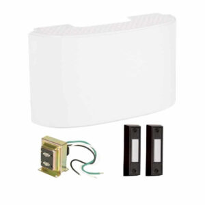
Setup, pairing, and troubleshooting for the CK2001 by Craftmade Wired Door Chime Kit with Curved Chime.
LEKTROLOK--MODELS 103 & 104RA DEADBOLT ELECTRIC LOCKS
Installation
- 345 Bayview Avenue
- Amityville, New York 11701
- For Sales and Repairs 1-800-ALA-LOCK
- For Technical Service 1-800-645-9440
- © ALARM LOCK 2003
- The LEKTROLOK Models 103 and 104RA Deadbolt Electric
- Locks are compact units designed to fit narrow stile doors. Both
- models come complete with "keepers" (deadbolt holes) which
- make it simple to install on all types of doors or windows includ-
- ing single, pairs, double acting or overhead, either in-swinging or
- out-swinging. When the lock is aligned with the keeper, the
- deadbolt projects into the keeper thus locking the door. The
- deadbolt is retracted (and the door unlocked) by means of a re-
- mote switch, a key switch, time programmer or other electrical
- contact which interrupts the power. Both models are ideally
- suited to programmed locking and unlocking of laundromats,
- lobby doors, or other unattended areas. Use of a lighted push
- button switch at the door (Alarm Lock Model 191) assures that
- ANGLED KEEPER
- FLUSH KEEPER
- WI1192 4/03
- people inside the building can exit after Iock-up time; the door
- will relock automatically after exit. May be wired with smoke
- detectors and/or fire alarm systems for automatic unlocking in a
- fire emergency.
- MODELS AVAILABLE
- Model 103 is a standard "fail safe" unit which projects the dead-
- bolt only while power is "on". When the power is off, the dead-
- bolt retracts. Model 104RA ("Reverse Action") unlike the stan-
- dard unit is "fail secure" and will project the deadbolt only when
- the power is "off". When the power is "on", the deadbolt re-
- tracts.
- LEKTROLOK--MODEL 103/104RA
- ELECTRIC DEADBOLT
- MORTISE KEEPER. INSTALLED FLUSH
- (INSIDE THE DOOR FRAME). FOR USE
WITH WOOD DOOR FRAMES ONLY. 1
--- page break ---
Installation
Note: The deadbolt will not project unless the magnet is opposite the reed switch. The template supplied serves the majority of installations. If your installation is different, always maintain a 1/8î gap between the face of the lock and the keeper.
The lock should be mounted on the door frame (rather than the door) for ease of wiring. If in- stalling the lock with the plunger facing down, see special installation instructions on the next page. Before mounting the lock, provide for the electric wires to the lock.
After the lock and keeper are installed, place the magnet onto the keeper slot which faces the reed switch in the lock as shown in figure 1. After the magnet is in place, affix the aluminum plate into the keeper recess.
- MODEL 103 CONNECTIONS MODEL 104RA CONNECTIONS
- LOCK NORMALLY CLOSED LOCK NORMALLY OPEN SWITCH
- SWITCH(ES) (ES)
- BLACK RED
- BLACK BLACK
- 24-VOLT AC/DC 24-VOLT AC/DC
- TRANSFORMER TRANSFORMER
- MODEL 221 MODEL 221
Follow the above schematics for one or more switches as required. Note: Model 103 requires switches to be installed in series. It is normally energized and normally runs hot to the touch.
Model 104RA Reverse Action requires switches to be installed in parallel.
- FIGURE 1 MAGNET and REED
- SWITCH must be
- mounted opposite
- each other
- MAGNET
- REED SWITCH
- DEADBOLT
- KEEPER HOLE
- The magnet inside the keeper hole assembly must be mounted op-
posite the reed switch or the deadbolt will not work properly.
Specifications
DIMENSIONS: 1æ" W x 6æ" L (including keeper). Bolt diameter is 5/8" and projects 5/8". FINISH: Lock and keeper--painted aluminum.
WEIGHT: 3 lbs., including keepers. POWER REQUIREMENTS: 600mA@24VAC or VDC (103). 12V version available a extra cost. LOCKING BOLT: Actuated by a continuous-duty solenoid. 2
--- page break ---
WHEN INSTALLING THE LOCK WITH PLUNGER FACING DOWN When installing the lock in a vertical position with the plunger facing down, we suggest replacing the colored spring (7 coils) with a stronger one (not colored, 5 coils) included in the box. To replace the spring, refer to the diagram below and replace it as follows: 1. Remove the lock cover. 2.
Remove the screws holding the solenoid to the base. 3. Slide the solenoid out of the base. 4. Remove the colored spring (7 coils) and replace it with the spring (not colored, 5 coils) included in the box. 5.
Slide the solenoid back into the base. 6. Fasten and tighten the screws holding the solenoid to the base. 7. Fasten the lock cover.
Replacing the spring on Model 103/104 Lock 3
--- page break ---
APPLICATION EXAMPLES Mount lock on door frame (rather than the door) for ease of wiring. Examples are shown below: SPACER INSWINGING HORIZONTAL INSTALLATION. DEADBOLT ON FRAME (WITH SPACER) AND A FLUSH KEEPER SCREWED INTO DOOR (SEE BELOW IMAGE).
OUTSWINGING VERTICAL INSTALLATION.
- DEADBOLT ON FRAME,
- ANGLED KEEPER ON DOOR
- SEE ABOVE IMAGE
- INSTALL KEEPER BEFORE DEADBOLT.
- MORTISE KEEPER. MAGNET IS MORTISED
- (EMBEDDED) INSIDE THE DOOR FRAME AND
- KEEPER IS INSTALLED FLUSH. FOR USE WITH
- WOOD DOOR FRAMES ONLY. (METAL FRAMES
WILL DISSIPATE MAGNET STRENGTH). INSWINGING VERTICAL INSTALLATION.
- DEADBOLT ON FRAME INSWINGING HORIZONTAL
- FLUSH KEEPER ATTACHED TO TOP INSTALLATION NEAR FLOOR
- EDGE OF DOOR
4