
BALERT-W User Manual
Setup, pairing, and troubleshooting for the BALERT-W Wireless Reflector Beam Entry Alert Door Chime by Seco-Larm.
- Wireless Entry Alert System
- E-931CS22RFCQ
- Installation Manual
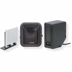
The ENFORCER Wireless Entry Alert System is a self-contained easy-to-install alert system for commercial or home applications. Each set contains a reflective photoelectric beam sensor that, when tripped, communicates wirelessly with a speaker installed up to 328ft (100m) away*. Additional speakers may be installed to alert more than one area on the property.
- For monitoring a driveway or for use as an entrance indicator
- No wiring necessary between sensor and speaker
- Sensor range: Up to 22ft (7m)
- Sensor is weatherproof for outdoor use
- Speaker makes chime or alarm sound if beam is interrupted
Wireless Range
Up to 328ft (100m) between the sensor and speaker
- Each sensor can be paired with an unlimited number of speakers
- Each speaker can be paired with up to 5 sensors *Range may vary depending on the installation and operating environment. --- page break --- Wireless Entry Alert System Parts List Specifications Sensor Speaker Current draw
Dimensions
31/ "x29/ "x11/ " (82x66x38 mm) 31/ "x215/ "x19/ " (83x75x40 mm) 4 Range may vary depending on the installation and operating environment.
Overview
11/2" 29/16" ø31/ " 19/16" 4 Alert tone 215/16" (66mm) Alignment 31/4" LED (82mm)
- 2.5mm DC Jack
- Speaker Setup
- (ø82mm)
- selector (75mm)
- ø3/ " 1 Timer Volume
- 16 3 /4"
- (ø4mm) (83mm)
- Cable length, Counter output Timer Volume 2.5mm
- 97/8" (250mm) DC Jack
- Mode button
using the alert tone selection switch on the side of the speaker. Adjust the volume by using the included Phillips screwdriver to turn the volume adjustment screw. Turning clockwise increases the volume; counter-clockwise decreases the volume.
Adjust the timer duration by turning the timer adjustment screw using the included screwdriver. Maximum clockwise sets the timer for 30 seconds; maximum counter-clockwise sets the timer for 3 seconds.
--- page break ---
- Wireless Entry Alert System
- Mounting and Installation
- 1. Determine the mounting location for each component.
- a. The reflector and sensor should be installed facing each other
- about 2ft (61cm) off the ground.
- b. Avoid locations where sunlight or other direct beam of light could
- enter the sensing spot on the sensor face.
- c. Install the speaker within 328ft (100m) of the sensor, noting that
- obstructions or interference that may reduce the range.
- 2. Attach the sensor to its bracket (see Fig. 1) and mount the bracket to a
- wall or other surface.
- 3. Mount the reflector to a flat surface opposite the sensor so that the
- reflector is aligned with the sensor face (see Fig. 2).
- 4. Connect an included power adapter to the sensor. Align by slowly
changing the angles of the sensor and reflector. NOTE: The red LED turns off when the alignment is correct.
- 5. Mount the speaker where it can be easily heard. For direct surface
- mount, drill a small hole and insert the provided screw without
- tightening it fully to hang the speaker on the screw. Otherwise, attach
it to its bracket and mount the bracket where desired (see Fig. 3). 6. Connect an included power adapter to the speaker and test. Fig. 1 - Sensor Sensor face
- Fig. 2 - Reflector
- Fig. 3 - Speaker
- Bracket
- Wall- mounting
- mount holes
- screw
- Pairing Optional Additional Speakers (E-931ACC-CQ)
Use one of the two methods below to pair an optional additional speaker with the sensor. NOTES The speaker included with the Wireless Entry Alert System is pre-paired with the sensor. When pairing an additional speaker, release the mode switch immediately after 2 seconds and hearing the long beep.
Pressing the switch for more than 5 seconds will delete the memory. Method 1 Method 2 1. Use the mode adjustment pin 1.
Remove the sensor's side panel to press and hold the mode with the included screwdriver. switch until you hear a long 2. Follow step 1 of Method 1.
- beep. The speaker is now in 3. Press the sensor’s learning button
- learning mode. once. You will hear one beep.
- 2. Trigger the sensor by breaking 4. After 10 seconds, one long beep
its beam. You will hear one indicates successful pairing. beep.
- 3. After 10 seconds, one long
- beep indicates successful
- Learning button
- pairing.
- Clearing the Memory
- 1. Use the included mode
- adjustment pin to press and
- hold the mode switch until you
- hear a long beep and two short
- beeps after five seconds.
- 2. Release the mode button and
- the memory has been cleared.
- Connecting an Optional Counter (E-931ACC-CQ)
To install a counter (sold separately), follow these instructions. 1. Plug the counter into the counter output jack of the speaker (see Fig. 4).
- 2. Test the counter. Each time the beam is broken, the counter should
- automatically increase by 1.
- 3. Manually add or subtract 1 by pressing the "+" or "-" buttons
- 4. Reset the counter by pressing RESET.
- Fig. 4
--- page break ---
- Wireless Entry Alert System
- Sample Applications
- Storefront Main Entrance Driveway
Troubleshooting
Sensor red LED does not
- Check power adapter and cable turn ON
- Remove any shiny metallic objects near installation site Sensor red LED does not
- Realign the sensor and reflector turn OFF
- Clean the sensor cover and remove any obstacles
- Make sure speaker is switched to Chime or Alarm
- If using Alarm, make sure alarm duration is long enough Speaker does not sound
- Try pairing the sensor to the speaker. See Pairing the Sensor and Optional Additional Speaker on page 3 Accessories Wireless Digital Square Reflector Door Frame Speaker Counter Reflector Hood Bracket E-931ACC-SFQ E-931ACC-CQ E-931ACC-R2Q E-931ACC-HR1Q E-931ACC-BLS8Q
FCC Compliance
STATEMENT FCC ID: K4E931CS22RF Information to the user: This equipment has been tested and found to comply with the limits for a class B digital device, pursuant to part 15 of the FCC rules. These limits are designed to provide reasonable protection against harmful interference when the equipment is operated in a commercial environment. This equipment generates, uses, and can radiate radio frequency energy and, if not installed and used in accordance with the instruction manual, may cause harmful interference to radio communications.
Operation of this equipment in a residential area is likely to cause harmful interference in which case the user will be required to correct the interference at his or her own expense. CAUTION: This sensor was not designed to prevent bodily injury or loss of life. Use of this sensor in certain security applications may be regulated by local laws or codes Users and installers of this product are responsible for ensuring that the installation and configuration of this product complies with all national, state, and local laws and codes.
SECO-LARM will not be held responsible for the use of this product in violation of any current laws or codes. California Proposition 65 Warning: These products may contain chemicals which are known to the State of California to cause cancer and birth defects or other reproductive harm. For more information, go to www.P65Warnings.ca.gov.
Warranty
This SECO-LARM product is warranted against defects in material and workmanship while used in normal service for one (1) year from the date of sale to the original customer. SECO-LARM’s obligation is limited to the repair or replacement of any defective part if the unit is returned, transportation prepaid, to SECO-LARM. This Warranty is void if damage is caused by or attributed to acts of God, physical or electrical misuse or abuse, neglect, repair or alteration, improper or abnormal usage, or faulty installation, or if for any other reason SECO-LARM determines that such equipment is not operating properly as a result of causes other than defects in material and workmanship.
The sole obligation of SECO-LARM and the purchaser’s exclusive remedy, shall be limited to the replacement or repair only, at SECO-LARM’s option. In no event shall SECO-LARM be liable for any special, collateral, incidental, or consequential personal or property damage of any kind to the purchaser or anyone else. NOTICE: The SECO-LARM policy is one of continual development and improvement.
For that reason, SECO LARM reserves the right to change
Specifications
without notice. SECO-LARM is also not responsible for misprints. All trademarks are the property of SECO-LARM U.S.A., Inc. or their respective owners.
Copyright © 2022 SECO-LARM U.S.A., Inc. All rights reserved. ® SECO-LARM U.S.A., Inc. PITSW3 16842 Millikan Avenue, Irvine, CA 92606 Website: www.seco-larm.com Phone: (949) 261-2999 | (800) 662-0800 Email: sales@seco-larm.com MI_E-931CS22RFCQ_220822.docx