
ERA-UTRXPG User Manual
Setup, pairing, and troubleshooting for the ERA-UTRXPG Door Entry Chime for Business Includes Doorbell Button & Receiver.
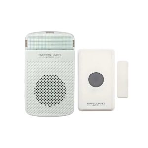
ERA-UTRXPG (ERA-RXPG + ERA-UTX)
Introduction
The ERA-UTRXPG is a long range wireless door chime kit with the following two components; the ERA-RXPG plugin receiver & the ERA-UTX. This manual outlines how to program the ERA-UTX push button/door contact to the ERA-RXPG receiver, & will serve as the product manual for the kit & both individual products in the kit.
Helpful Notes
- All ERA transmitters are compatible with all ERA receivers.
- The ERA-UTX may be used as a push button or door contact & must be programmed to a ERA compatible receiver to operated.
- The push button/door contact is outdoor rated & constructed of a heavy- duty ABS plastic.
- The ERA-RXPG is a plugin receiver & is indoor rated only.
- Push button measures 3.38” x 1.94” x .81”.
- The receiver measures 4.75”H x 2.75”W x 1.5” D
- Up to 12 different ERA transmitter/sensors may be programmed to each ERA compatible receiver.
- There is not limit to the number of receivers a transmitter/sensor may be programmed to.
- The receiver has three modes of operation; 1) sound only, 2) strobe only, or 3) sound & strobe.
- The receiver features four levels of volume + mute.
- There are 12 available melodies to choose from on the receiver.
- Each programmed transmitter/sensor can have a different melody on the receiver if desired. ERA-UTX
Battery Installation
- 1.Flip the case over & remove the four(4) gray
- silicon grommets. Remove each of the screws
- under the grommets using a Phillips head
- screwdriver.
- 2. Separate the top half of case from lower half of
- the case.
- 3. Install the included CR-2 battery in the holder
- (see figure 1).
- 4. Replace cover, insert & tighten screws, re-insert
- silicon grommets.
- 5. Test by pressing gray center push or by
- separating small magnet from side of the larger
- unit. A red LED should glow inside gray center
- push.
- 4.Follow the instructions for "Pair (figure 1)
- Transmitter to Receiver".
- 5. Note: When battery gets weak, it will cause
- receiver to double-play the programmed melody
when triggered.
Pairing the Transmitter
- The transmitter works with all ERA receivers. Basic programming calls for
- the user to program a transmitter to the receiver & select a melody for the
- receiver to play when triggered by the transmitter. In the example below,
- the transmitter will be programmed to the ERA-RXPG plugin receiver. If
- you are using a different ERA receiver, follow the programming
- instructions for that receiver to put the receiver in programming mode &
- to change the melody.
- (figure 2)
- 1. Ensure the ERA-RXPG is plugged into a standard wall outlet.
- 2. On the ERA-RXPG receiver, hold down the "mode" button (lower button
- in figure 2) until you hear a short tone sound & the red LED (inside the
- front lens cover) begins to blink. This denotes the unit is in
- programming mode. Release this button.
- 3. Scroll through available melodies by pressing the melody selector
- button. Stop pushing this button when you hear the sound you want
- the respective push button to play.
- 4. Push the center push on the push button. The receiver will play a quick
chime sound notifying the transmitter is programmed to the receiver. The red LED should still be blinking.
- 5. If you want to program a second transmitter (push button, door contact,
- motion sensor, or driveway sensor) push the melody selector button
- (the button on top) to scroll through available melodies. Once you have
- the sound you want, stop pressing the melody selector button and
- repeat step 4 above, triggering the sensor/transmitter.
- 6. Once you have programmed all the transmitter(s), exit programming
- mode by holding down the "mode" button until you hear a short tone
- sound & the red LED disappears (approx 3 seconds).
- Test the
Programming
of Transmitter to Receiver:
- Ensure the ERA-RXPG receiver is plugged in & the battery is installed in the ERA-PBTX push button.
- Push the center button of the ERA-PBTX push button. --- page break --- Test the Programming of Transmitter to Receiver (cont):
- When pressed, the green halo around the center push should brightly illuminate.
- When triggered the receiver should play the selected melody and/or flash. Make sure the receiver is set to sound mode by moving the selector switch on the side of the receiver to sound only or sound + strobe (middle or lower position of selector switch). Mounting the Push Button: Ensure you have programmed & tested the push button prior to mounting. There are two
Mounting
for the ERA-UTX.
- The transmitter can be mounted to any wall using the mounting bracket. (Figure 3)
- The mounting bracket is located on the back of the ERA-UTX and can be removed by simply sliding it off.
- Position the bracket were you would like it and place two screws in the holes provided. To place the ERA-UTX back, simply slide it over the bracket.
- If mounting the ERA-UTX outdoors it is recommended to ensure the silicone plugs in the screw holes at the back are of the case are in place to prevent (figure 3) moisture from entering the case. Using the Magnetic Contact: The magnetic contact can be used on most doors/windows with a gap of less than ½ inch.
- Mount the push button on the door jam with the screws provided.
- Mount the magnet on the door (within ½” of the push button) with the screws provided.
- After mounting the magnet on the door snap the cover on the magnet case.
- The magnetic contact can be used on either side of the push button. (Figure 4) (figure 4) Deleting the Memory of the ERA-RXPG:
- On the ERA-RXPG receiver, hold down the "mode" button (lower button in figure 2) until you hear a short tone sound & the red LED (inside the front lens cover) begins to blink. This denotes the unit is in programming mode. Release this button. Deleting the Memory of the ERA-RXPG (cont:)
- Simultaneously hold both the "mode" & "volume" button for approximately 5 seconds until you hear a quick chime sound.
- This notifies that the memory of the ERA-RXPG is been erased. Low Battery Indicator: When the battery in the ERA-PBTX is low & needs to be replaced, it will signal the receiver to double play the programmed melody on the receiver when triggered. For example, if you have programmed the "ding-dong" sound for the push button to play on the receiver, when the battery in the push button is low, the receiver will play "ding- dong...ding-dong" when triggered to notify you to change the battery.
Programming
with Other Receivers:
- The ERA-PBTX is compatible with the ERA-VPRX Portable Receiver &
- the ERA-DCRX Receiver. The programming is very similar for these
- receivers as well. The only change is how to put the respective
- receiver into programming mode, choosing a melody, & changing the
- zone. Please consult the manual for the specific receiver when
- programming.
- TECHNICAL SUPPORT
- If you encounter any difficulties in the operation or programming of
- this product after reading the manual, please contact us. You can
- reach us by phone at 904-245-1184 from 8:00 AM to 5:00 PM Monday -
- Friday (Eastern Standard Time). We will be happy to answer your questions
and help you in any way possible.
Warranty
- Safeguard Supply warrants this product to be free of defects in material and workmanship
- for a period of one year from the date of purchase. This warranty does not cover damage
- resulting from accident, abuse, act of God or improper operation. If this product does
- become defective, simply return it to Safeguard Supply. Please include a note describing
the troubles along with your name and return address as well as the original sales receipt. If the product is covered under warranty it will be repaired or replaced at no charge. If it is not covered by warranty, you will be notified of any charges before work is done.
- Safeguard Supply, 2260 Moon Station Ct. NW #110, Kennesaw, GA 30144
- Phone: (678) 214-4212, www.safeguardsupply.com, info@safeguardsupply.com.
- Legal Notices
- This device complies with Part 15 of the FCC Rules. Operation is subject to the following
- two conditions: (1) this device may not cause harmful interference, and (2) this device
- must accept any interference received, including interference that may cause undesired
- operation. changes or modifications not expressly approved by the party responsible for
- compliance could void the user’s authority to operate the equipment.
- This equipment has been tested and found to comply with the limits for a Class B digital
- device, pursuant to Part 15 of the FCC Rules. These limits are designed to provide
- reasonable protection against harmful interference in a residential installation. This
- equipment generates, uses and can radiate radio frequency energy and, if not installed
- and used in accordance with the instructions, may cause harmful interference to radio
- communications. However, there is no guarantee that interference will not occur in a
- particular installation.
- If this equipment does cause harmful interference to radio or television reception, which
- can be determined by turning the equipment off and on, the user is encouraged to try to
correct the interference by one or more of the following measures:
- Reorient or relocate the receiving antenna.
- Increase the separation between the equipment and receiver.
- Connect the equipment into an outlet on a circuit different from that to which the receiver is connected.
- Consult the dealer or an experienced radio/TV technician for help. WARNING: Cancer and Reproductive Harm. Go to www.P65Warnings.ca.gov for more information.